ESP8266 Wi-Fi based 7-Segment Display clock
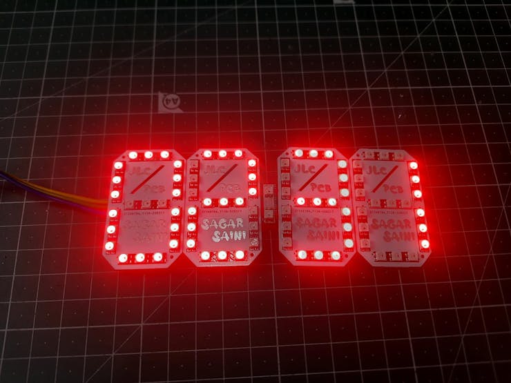
Hello guys, I made want to make a 7-segment display. But this time with bigger digits and RGB effects. Because this can be used to display some readings like Clock with Nodemcu, temperature monitoring using Arduino. Also, with an option of color changing after each second or next reading. I also have the similar one, which I designed a while back. That design has some Led orientation problems.
Because last time I used 2 LED’s to display per segment, our eye can’t regonize the digits too fast and accurate. Means we need a focus; I am happy with the design but now it’s time for update. JLCPCB is always with me to provide good PCB prototype and SMT assembly service solutions.
This mini led has voltage ratings: 3.0v to 5.5volts @16mA (for each Led). Our NodeMCU has 3.3-volt regulator, to drive all the LED’s properly.
LED WS2812B 3030:
I used ws2812 Neo pixel led, which comes with integrated ic so that we can address each segment separately. Not only the LEDs are addressable but also the color can be changed per pixel changing the digital value between 0-255(8-bit value).
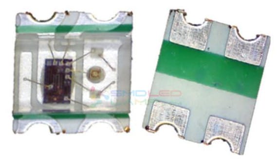
This led comes with 4 pins, the configuration of pins can be seen in the picture mentioned above. Also, these Led’s come with Data IN and Data OUT function, which make them more interesting and through this we can join them to show text or data.
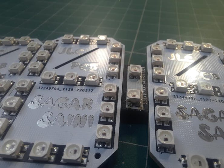
Making 7 segment display using neo pixel led:
To make the panel, first we have to take a closer look on actual lcd. So that we can copy the arrangement of segments and design a code for that.
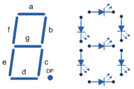
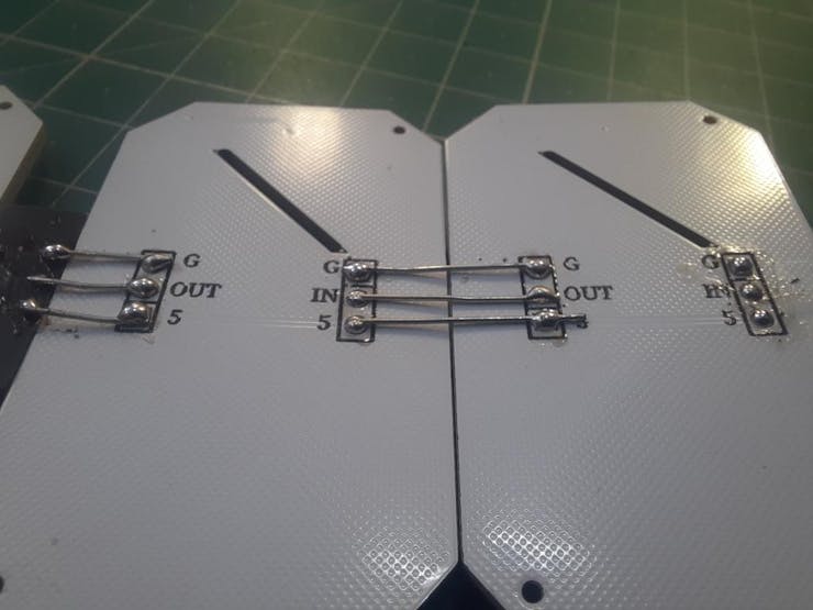
So here, segments are named as A, B, C…… to G, so to connect all the segments we use series data and parallel power method. All the power lines, GND and VCC are joined in parallel to all the led’s. Data OUT is supplied to Data IN of next Led in series. Always connect Dout of first panel to Din of second.
Dash connections:
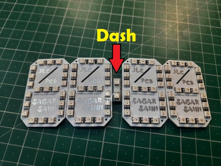
To connect the hours and minutes panel, A small PCB is there in between named as Dash, contains 2 LED’s as binary digits. These 2 LED’s glow after each second.
I used JLCPCB SMT assembly service for these good looking PCBs, here is the full review of the SMT assembly service. White color PCB, 1.6mm thickness and HASL finish is looking pretty damn good with JLCPCB SMT Assembly service. These Boards are fully assembled by JLCPCB, means all the components and soldering work is done by them. Why not to try this offer, JLCPCB SMT assembly service is staring from $8 and if you sign-up using this link, you will get free coupons of worth $30 and newcomer rewards.
Need of NodeMCU/ESP8266:
ESP8266 is integrated with a 32-bit Tensilica processor, standard digital peripheral interfaces.
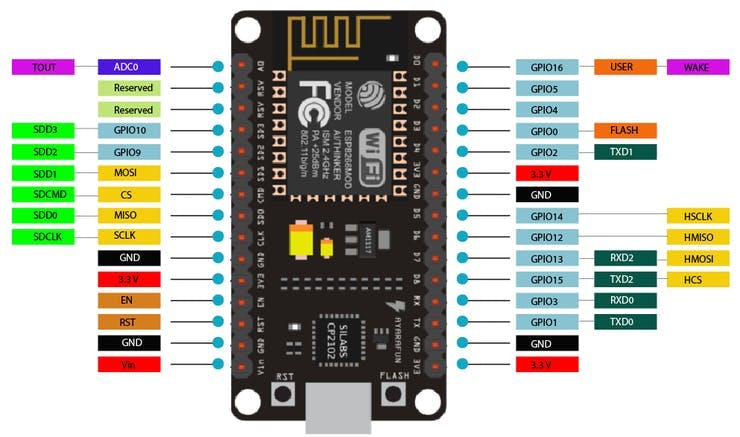
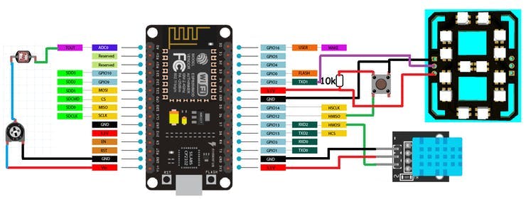
Our Esp8266 has on board Wi-Fi support, through this we can adjust the time over internet without any RTC(real time clock) module. This will reduce the connections and make this project simple.If you are using my code, then there are 2 extra features you may add in this 7-segment clock.1) Temperature and humidity using tactile switch.Add a DHT11 sensor on pin number 13 and a tactile button on pin number 12 to get the temperature values on screen in Celcius or Farenheit.
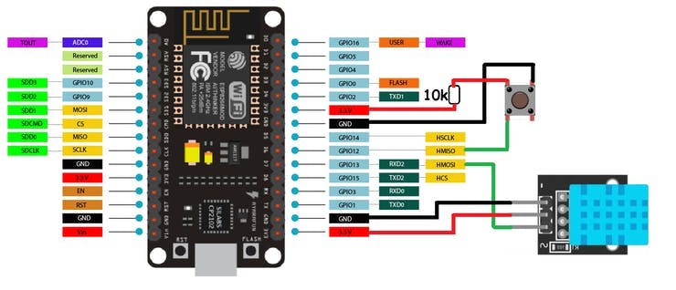
Connect the button pin 12 to 5volt using a 10k resistor and the other end to GND. Means when the button pin is pull down to GND, Display will show temperature readings. The code will also work without this Temperature sensor, so if you want to keep it simple there is no need of these connections.2) Brightness control using LDR sensor at pin A0.
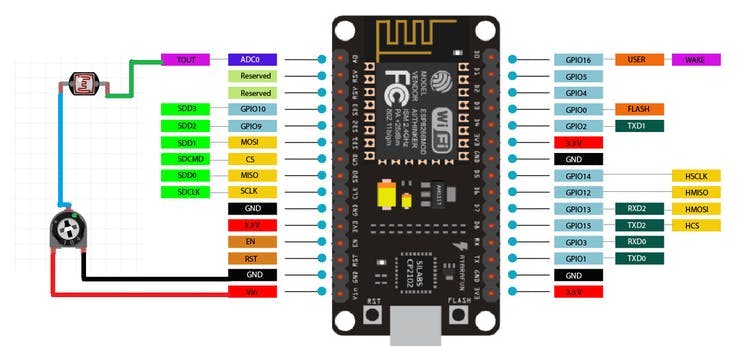
Add a LDR sensor with 10k resistor by making a resistor divider network on A0 pin, this will change the brightness accordingly. High brightness in day time, low in night. The code will also work without these sensors if you don’t want adjustable brightness, it will locked on default settings.
7- Segment Clock:
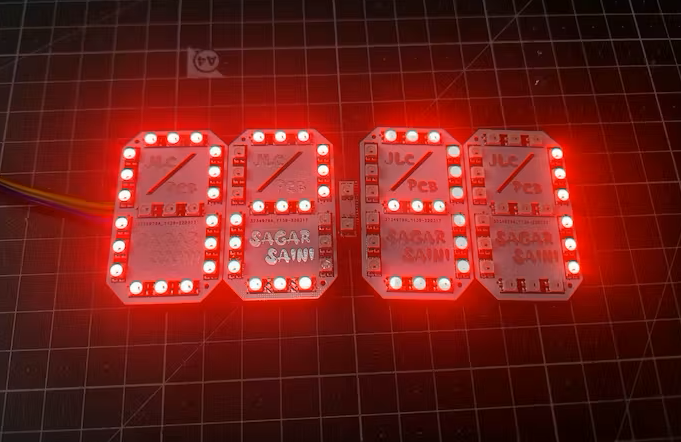
I designed the circuit in EasyEDA for each segment here I am using 3 LED’s. So, a total of 21 led’s per panel is required to make this configuration. I made the connection pins at bottom layer so that the connection and wiring is not visible to second person.
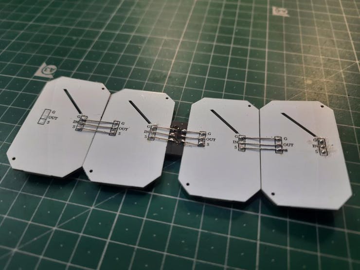
Keeping the formfactor, Layers and track data in mind I designed the PCB and generate the CPL, BOM along with Gerber files. If you want to use same designs as mine Download them from here. And for more information you can join the community on Instagram Sagar_saini_7294. Now, we have 4 panels and one dash. Connect 2 panels in series in pair.Now connect dash in between and connect NodeMCU using schematics given below:
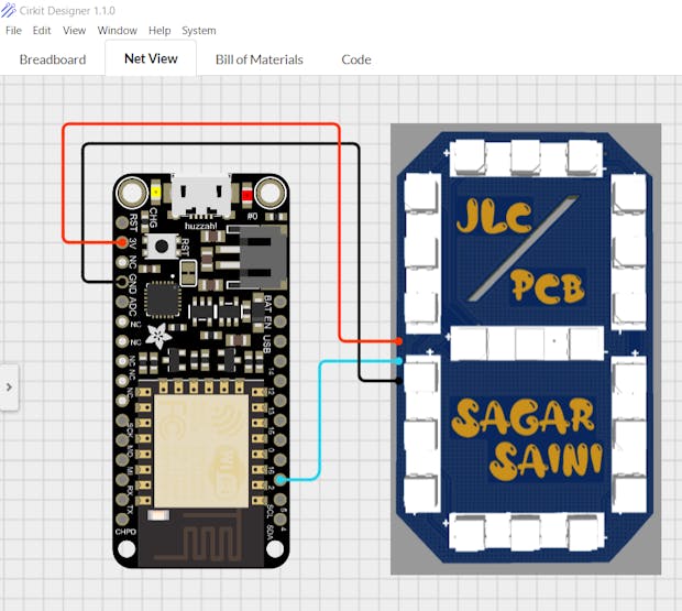
I am using cirkit designer software for along time, I think this is the best way to express and present the circuits. You can use this wire diagram, breadboard circuit along with custom component creating in school and college presentations. Also, Code compilation, BOM and some new components are recently added.
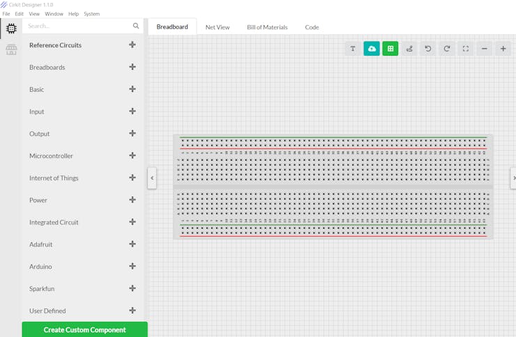
Download cirkit designer from HereCirkit Designer Is a one-stop-shop desktop application for designing and documenting circuits and electronics projects. With Cirkit Designer, you can lay out realistic circuit diagrams that are linked to a bill-of-materials so that you can seamlessly order the parts to your circuit.
Code:
1) First initialize the code using librarie
#include <ESP8266WiFi.h>
#include <Adafruit_NeoPixel.h>
#include <WiFiUdp.h>
#include <NTPClient.h>
#include <TimeLib.h>
#include <DHT.h>
#include <Adafruit_Sensor.h>
2) Define all pixels, I/O pins, sensor pins:
#define PIXEL_PER_SEGMENT 3 // Number of LEDs in each Segment
#define PIXEL_DIGITS 4 // Number of connected Digits
#define PIXEL_PIN 2 // GPIO Pin
#define PIXEL_DASH 1 // Binary segment
#define LDR_PIN A0 // LDR pin
#define DHT_PIN 13 // DHT Sensor pin
#define BUTTON_PIN 12 // Button pin
3) For time format connect Internet using Wi-Fi to ESP8266
WiFi.begin(ssid, password);
Serial.print("Connecting.");
while ( WiFi.status() != WL_CONNECTED )
4) Time settings on Pixel
void disp_Time() {
clearDisplay();
writeDigit(0, Hour / 10);
writeDigit(1, Hour % 10);
writeDigit(2, Minute / 10);
writeDigit(3, Minute % 10);
writeDigit(4, Second / 10);
writeDigit(5, Second % 10);
disp_Dash();
5) Color setting on panels:
if (index == 0 || index == 1 ) color = strip.Color(0, Brightness, 0);
if (index == 2 || index == 3 ) color = strip.Color(0, Brightness, 0);
if (index == 4 || index == 5 ) color = strip.Color(Brightness, 0, 0);
This is a brief about code, also the code has temperature and auto time options. Temperature mode can be selected using tactile switch on Digital pin 12.
Working code:
#include <ESP8266WiFi.h>
#include <Adafruit_NeoPixel.h>
#include <WiFiUdp.h>
#include <NTPClient.h>
#include <TimeLib.h>
#include <DHT.h>
#include <Adafruit_Sensor.h>

#define PIXEL_PER_SEGMENT  3     // Number of LEDs in each Segment
#define PIXEL_DIGITS       4     // Number of connected Digits
#define PIXEL_PIN          2     // GPIO Pin
#define PIXEL_DASH         1    // Binary segment

#define LDR_PIN       A0    // LDR pin
#define DHT_PIN       13    // DHT Sensor pin
#define BUTTON_PIN    12    // Button pin

// Uncomment the type of sensor in use
#define DHT_TYPE    DHT11     // DHT 11
//#define DHT_TYPE    DHT22     // DHT 22 (AM2302)
//#define DHT_TYPE    DHT21     // DHT 21 (AM2301)

#define TIME_FORMAT        12    // 12 = 12 hours format || 24 = 24 hours format

Adafruit_NeoPixel strip = Adafruit_NeoPixel((PIXEL_PER_SEGMENT * 7 * PIXEL_DIGITS) + (PIXEL_DASH * 2), PIXEL_PIN, NEO_GRB + NEO_KHZ800);
DHT dht(DHT_PIN, DHT_TYPE);

// set Wi-Fi SSID and password
const char *ssid     = "Hackster";
const char *password = "*************";

WiFiUDP ntpUDP;
// 'time.nist.gov' is used (default server) with +1 hour offset (3600 seconds) 60 seconds (60000 milliseconds) update interval
NTPClient timeClient(ntpUDP, "time.nist.gov", 19800, 60000); //GMT+5:30 : 5*3600+30*60=19800

int period = 2000;   //Update frequency
unsigned long time_now = 0;
int Second, Minute, Hour;

// set default brightness
int Brightness = 40;
// current temperature, updated in loop()
int Temperature;

bool Show_Temp = false;

//Digits array
byte digits[12] = {
  //abcdefg
  0b1111110,     // 0
  0b0110000,     // 1
  0b1101101,     // 2
  0b1111001,     // 3
  0b0110011,     // 4
  0b1011011,     // 5
  0b1011111,     // 6
  0b1110000,     // 7
  0b1111111,     // 8
  0b1110011,      // 9
  0b1001110,     // C
  0b1000111,     // F
};

//Clear all the Pixels
void clearDisplay() {
  for (int i = 0; i < strip.numPixels(); i++) {
    strip.setPixelColor(i, strip.Color(0, 0, 0));
  }
  strip.show();
}

void setup() {
  Serial.begin(115200);
  strip.begin();
  strip.show();

  dht.begin();
  pinMode(BUTTON_PIN, INPUT);

  WiFi.begin(ssid, password);
  Serial.print("Connecting.");
  while ( WiFi.status() != WL_CONNECTED ) {
    delay(500);
    Serial.print(".");
  }
  Serial.println("connected");
  timeClient.begin();
  delay(10);
}

void loop() {
  if (WiFi.status() == WL_CONNECTED) { // check WiFi connection status
    int sensor_val = analogRead(LDR_PIN);
    Brightness =40;
    timeClient.update();
    int Hours;
    unsigned long unix_epoch = timeClient.getEpochTime();   // get UNIX Epoch time
    Second = second(unix_epoch);                            // get seconds
    Minute = minute(unix_epoch);                            // get minutes
    Hours  = hour(unix_epoch);                              // get hours

    if (TIME_FORMAT == 12) {
      if (Hours > 12) {
        Hour = Hours - 12;
      }
      else
        Hour = Hours;
    }
    else
      Hour = Hours;
  }

  if (digitalRead(BUTTON_PIN) == LOW) {
    Show_Temp = true;
  }
  else
    Show_Temp = false;

  if (Show_Temp) {
    Temperature = dht.readTemperature();
    Serial.println(Temperature);
    clearDisplay();
    writeDigit(0, Temperature / 10);
    writeDigit(1, Temperature % 10);
    writeDigit(2, 10);
    strip.setPixelColor(28, strip.Color(Brightness, Brightness,  Brightness));
    strip.show();
    delay(3000);
    clearDisplay();
    Show_Temp = false;
  }
  while (millis() > time_now + period) {
    time_now = millis();
    disp_Time();     // Show Time
  }
}

void disp_Time() {
  clearDisplay();
  writeDigit(0, Hour / 10);
  writeDigit(1, Hour % 10);
  writeDigit(2, Minute / 10);
  writeDigit(3, Minute % 10);
  writeDigit(4, Second / 10);
  writeDigit(5, Second % 10);
  disp_Dash();
  strip.show();
}

void disp_Dash() {
  int dot, dash;
  for (int i = 0; i < 2; i++) {
    dot = 2 * (PIXEL_PER_SEGMENT * 7) + i;
    for (int j = 0; j < PIXEL_DASH; j++) {
      dash = dot + j * (2 * (PIXEL_PER_SEGMENT * 7) + 2);
      Second % 2 == 0 ? strip.setPixelColor(dash, strip.Color(0,Brightness ,0)) : strip.setPixelColor(dash, strip.Color(0, Brightness,0));
    }
  }
}

void writeDigit(int index, int val) {
  byte digit = digits[val];
  int margin;
  if (index == 0 || index == 1 ) margin = 0;
  if (index == 2 || index == 3 ) margin = 1;
  if (index == 4 || index == 5 ) margin = 2;
  for (int i = 6; i >= 0; i--) {
    int offset = index * (PIXEL_PER_SEGMENT * 7) + i * PIXEL_PER_SEGMENT + margin * 2;
    uint32_t color;
    if (digit & 0x01 != 0) {
      if (index == 0 || index == 1 ) color = strip.Color(Brightness, 0,  Brightness);
      if (index == 2 || index == 3 ) color = strip.Color(Brightness, 0,Brightness);
      if (index == 4 || index == 5 ) color = strip.Color(Brightness, 0,  0);
    }
    else
      color = strip.Color(0, 0, 0);

    for (int j = offset; j < offset + PIXEL_PER_SEGMENT; j++) {
      strip.setPixelColor(j, color);
    }
    digit = digit >> 1;
  }
}
Fully functional Circuit diagram:
PCB designs:
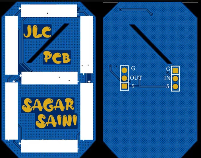
This is the main PCB design which is used to display the digits and other letters. Download all the Required files regarding this project from here.
JLCPCB Is the only PCB manufacturer providing SMT service in very cheap, yet the quality of boards is very good. I tested my all the Boards and they are working fine, all the components are okay. The soldering work is outstanding and cost is very less. Checkout to JLCPCB now with and turn your projects into products.
Troubleshooting:
1) Din is always connected to Dout in series with on e another, if connected in opposite or disconnected from anywhere whole setup stops working.
2) Connect the Dash as shown in figure above.
3) Make sure all the connections are properly soldered, dry soldering will cause change in data value and color.
4) Don’t heat the PCB too much, while Soldering and keep the temperature on 300*c.