Programming ESP8266 using Arduino IDE
Previously, I designed an esp8266 shield. And today we will about to know that how to program this esp8266. Because our shield has the same pinout as it is in ESP breakout. Now we will see how to do make all the connections and how to setup Arduino IDE for esp8266 boards.
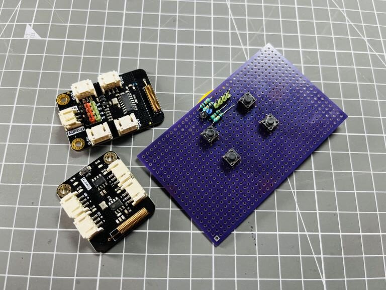
I ordered SMT assembly of these PCB boards from JLCPCB, it is quite easy to use JLCPCB SMT service because of its family websites. You can check SMT assembly from here starting from $8.
Setting up Arduino IDE:
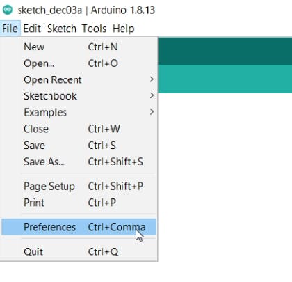
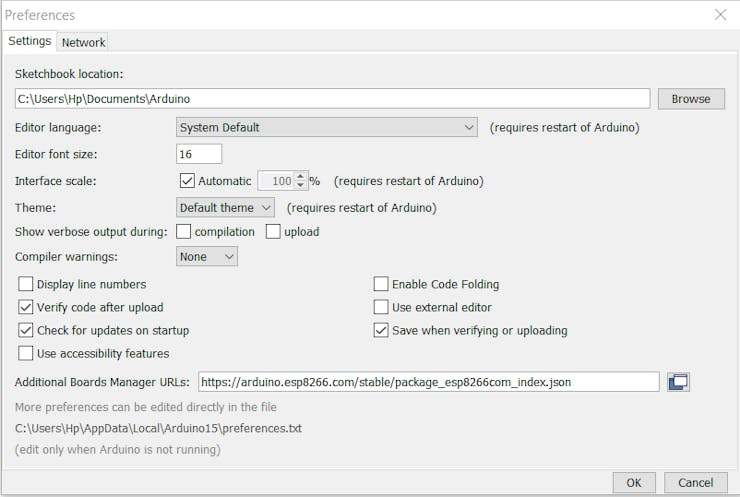
Open the Arduino IDE, Paste this code in the preference section under file menu.
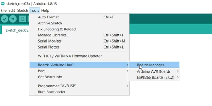
Then Go to the tools sections and install the ESP8266 boards from board manager.

Now you can see all the different esp8266 board manufacturers. Choose the used microcontroller.
Connection info and setup:
We can program the esp8266 using NODEMCU (esp8266 development board) or FTDI programmer (USB to serial programmer). Here are the connections info of the esp8266 shield with NODEMCU:
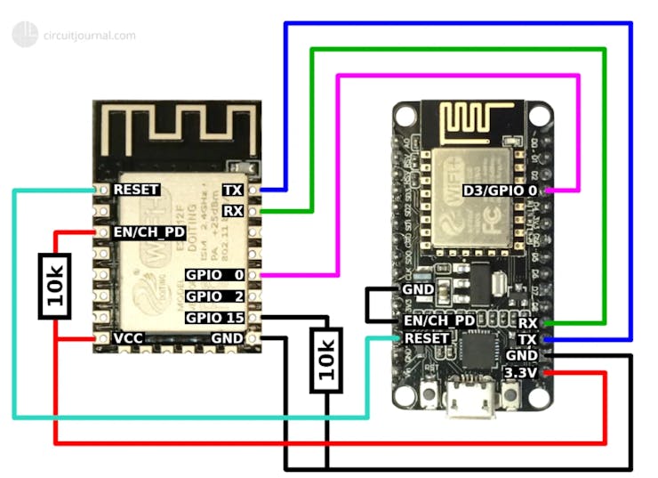
1) Pull down the ENABLE pin of NODEMCU directly connecting with ground. This will cut the programming connection of onboard microcontroller.
2) Connect RX to RX and TX pin to TX. Because now Esp8266 shield behave like an onboard Microcontroller.
3) Connect RESET of ESP8266 with reset of NODEMCU.
4) Connect GPIO0 of ESP8266 with GPIO0 of NODEMCU.
5) Pull down the GPIO15 of ESP8266 with 10k resistor.
6) Pull up the enable pin of ESP8266 with 10k resistor.
7) Connect VCC to 3.3volts and make all the GND connections.
Connections with Serial programmer:
The connection with ftdi232rl is given below. Follow these connection points:
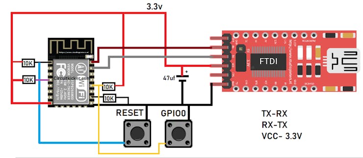
1) Pull up the enable pin with 10k resistor
2) Pull up the reset pin with 10k resistor and connect it to push button to do reset using GND.
3) Pull up the GPIO0 pin with 10k resistor and connect it push button to trigger while programming.
4) Pull down the GPIO 15 with 10k resistor.
5) Connect VCC to 3.3volts and make all the GND connections.
6) Connect 47uf capacitor between VCC and GND.
Because we are not using the transistor pair to do auto reset once start programming. So, a manual push is required of both push button alternatively when programming start and end. Push the GPIO0 tactile button when it starts to upload program and give a reset before and after programming done.
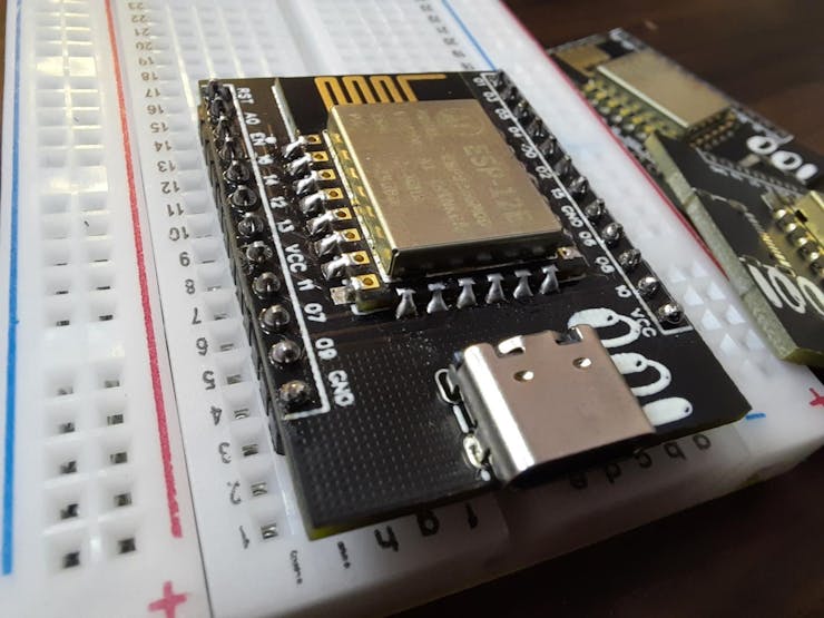
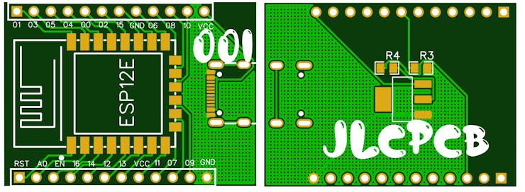
My esp8266 shield:
If you want to order the same files then get the BOM, Gerber and CPL from description. For my one I used, Black solder mask, 1.6mm thickness and Hasl finishing. Ordered using JLCPCB SMT assembly service.
Programming:
Programming can be done using Arduino IDE software. After making the connections, connect the USB to PC.
Then choose the proper COM port and the board type.
Then Upload the sketch and follow the other instructions given above.
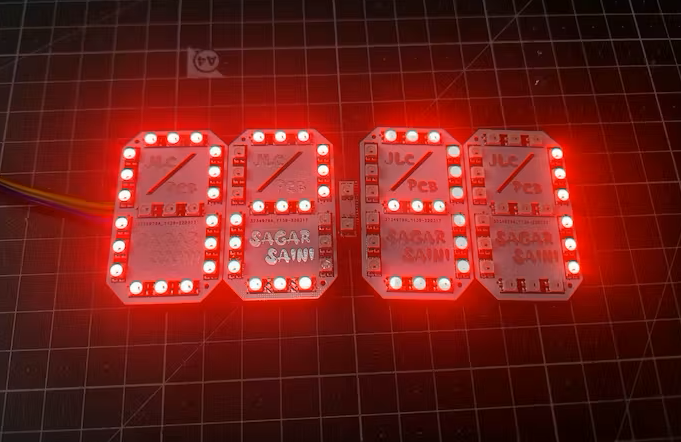
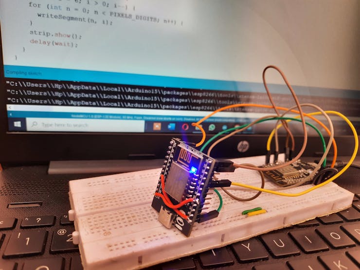
Working:
I am uploading my sketch using NODEMCU which is esp8266 development board. I am using a 7 segment RGB neo pixel for demonstration purpose. And it is working very fine with it. As usual esp8266 took a longer time to upload sketch than Arduino but it will upload the sketch properly.
I always prefer to use JLCPCB SMT assembly service because they are provide very good assembly service in very low price. SMT assembly is starting from just $8. Sign-up using this link and get free coupons of $54 to order PCB, PCBA, stencil and 3-D parts.