DIY SPY Wi-Fi Camera in LED BULB- ESP32Cam
Hi guys, Today we are going to make a SPY Wi-Fi camera using ESP32-CAM. I have some ideas to install that camera in a Led bulb cover or phone charger. Because some of the products related to this is also available on amazon. But I want to see the data over Wi-Fi or Internet. And that make sense, If we are using a non-Wi-Fi camera in this century without IOT, then our generation is way behind. https://www.youtube.com/embed/bZdA8q7XmD0
So, In this tutorial We will discuss the ESP32 cam boards in brief. Then, how to program them and how to make connection between camera module and wi-fi, some sort of coding knowledge. And finally, we will install whole setup into a Led BULB. And then we order the PCB prototypes of power supply from JLCPCB (5pcs in just $2).
ESP32 CAM- SPY Wi-Fi camera:
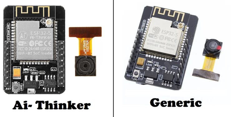
This camera module mostly available in two different products, one is from AI thinker and one is generic product. AI thinker is $2 costlier than generic, but both works fine. I am using generic one here. And both of them have same features, given below.
Specifications:
- – Ultra-small 802.11b/g/n Wi-Fi + BT/BLE SoC module
- – Low-power dual-core 32-bit CPU for application processors
- – Up to 240MHz, up to 600 DMIPS
- – Built-in 520 KB SRAM, external 4M PSRAM
- – Supports interfaces such as UART/SPI/I2C/PWM/ADC/DAC
- – Support OV2640 and OV7670 cameras with built-in flash
- – Support for images WiFI upload
- – Support TF card
- – Support multiple sleep modes
- – Support STA/AP/STA+AP working mode
- – Support Smart Config
- – Support for serial local upgrade and remote firmware upgrade (FOTA)
Programming and setup:
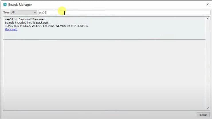
ESP32 board does not have usb port or onboard programmer chip, so we need an external programmer. Some cheap programmer boards are available like, ch340g and FTDI232RL which can do the job perfectly. For programming, Install Arduino IDE and download the Esp32 boards from board manger under the tools section.
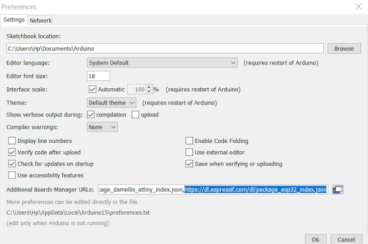
Paste this code in the preference section under files menu. If there is any already then add a comma and paste the code: https://dl.espressif.com/dl/package_esp32_index.json
Circuit diagram of SPY Wi-Fi camera:

Here I am using FTDI programmer and configure this with esp32 using the wires, as shown in the diagram below.If you wan to build our Own programmer board then check our tutorial: To get all the details about CH340 and FTDI programmer boards. Gerber files for this can be downloaded from here.

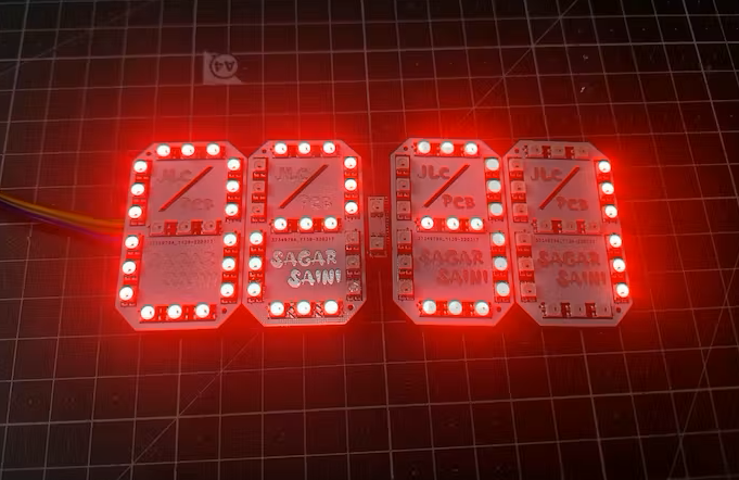
To build a professional one JLCPCB is the best option, They are providing 2 to 6 layer PCB’s just in $2. And If you Sign-up using my link(https://jlcpcb.com/SSRF), you will get 4 coupons worth $27. Which can be used to place the order on JLCPCB.
About Cirkit Designer Software:
Cirkit Designer Is a one-stop-shop desktop application for designing and documenting circuits and electronics projects. With Cirkit Designer, you can lay out realistic circuit diagrams that are linked to a bill-of-materials so that you can seamlessly order the parts to your circuit.

Download cirkit designer from HereIn the next release, Cirkit Designer is adding a code IDE with full support for compiling and programming Arduino boards, as well as a library of reference circuit designs (circuit templates including documentation, components and wiring, and code). Cirkit Designer will become the one-stop-shop to help you progress from concept to fully working breadboard prototypes. Simulation will also be added in the future, so that you can test your circuit before buying parts and building anything.
Settings of board and ports:
Choose ESP32 Wrover module match these same settings:
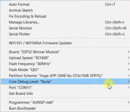
Partition scheme to: Huge APP (3MB No OTA), Flash mode, upload speed and frequency to same as shown in above image. Then upload the code and open the serial monitor.
Code:
1) This code is also available in EXAMPLES> ESP32> CAMERA> CameraWebServer.
Initalize this code and then select the proper camera module, If you are using Generic module, then wrover is okay.
//
// WARNING!!! PSRAM IC required for UXGA resolution and high JPEG quality
// Ensure ESP32 Wrover Module or other board with PSRAM is selected
// Partial images will be transmitted if image exceeds buffer size
//
// Select camera model
#define CAMERA_MODEL_WROVER_KIT // Has PSRAM
//#define CAMERA_MODEL_ESP_EYE // Has PSRAM
//#define CAMERA_MODEL_M5STACK_PSRAM // Has PSRAM
//#define CAMERA_MODEL_M5STACK_V2_PSRAM // M5Camera version B Has PSRAM
//#define CAMERA_MODEL_M5STACK_WIDE // Has PSRAM
//#define CAMERA_MODEL_M5STACK_ESP32CAM // No PSRAM
//#define CAMERA_MODEL_AI_THINKER // Has PSRAM
//#define CAMERA_MODEL_TTGO_T_JOURNAL // No PSRAM
2) Fill you Wi-Fi details, Username and password
const char* ssid = "*********";
const char* password = "*********";
3) If you are facing any error in programming see this video:https://www.youtube.com/embed/U7qbehy9aDo
Main code:
#include "esp_camera.h"
#include <WiFi.h>

//
// WARNING!!! PSRAM IC required for UXGA resolution and high JPEG quality
//            Ensure ESP32 Wrover Module or other board with PSRAM is selected
//            Partial images will be transmitted if image exceeds buffer size
//

// Select camera model
#define CAMERA_MODEL_WROVER_KIT // Has PSRAM
//#define CAMERA_MODEL_ESP_EYE // Has PSRAM
//#define CAMERA_MODEL_M5STACK_PSRAM // Has PSRAM
//#define CAMERA_MODEL_M5STACK_V2_PSRAM // M5Camera version B Has PSRAM
//#define CAMERA_MODEL_M5STACK_WIDE // Has PSRAM
//#define CAMERA_MODEL_M5STACK_ESP32CAM // No PSRAM
//#define CAMERA_MODEL_AI_THINKER // Has PSRAM
//#define CAMERA_MODEL_TTGO_T_JOURNAL // No PSRAM

#include "camera_pins.h"

const char* ssid = "*********";
const char* password = "*********";

void startCameraServer();

void setup() {
  Serial.begin(115200);
  Serial.setDebugOutput(true);
  Serial.println();

  camera_config_t config;
  config.ledc_channel = LEDC_CHANNEL_0;
  config.ledc_timer = LEDC_TIMER_0;
  config.pin_d0 = Y2_GPIO_NUM;
  config.pin_d1 = Y3_GPIO_NUM;
  config.pin_d2 = Y4_GPIO_NUM;
  config.pin_d3 = Y5_GPIO_NUM;
  config.pin_d4 = Y6_GPIO_NUM;
  config.pin_d5 = Y7_GPIO_NUM;
  config.pin_d6 = Y8_GPIO_NUM;
  config.pin_d7 = Y9_GPIO_NUM;
  config.pin_xclk = XCLK_GPIO_NUM;
  config.pin_pclk = PCLK_GPIO_NUM;
  config.pin_vsync = VSYNC_GPIO_NUM;
  config.pin_href = HREF_GPIO_NUM;
  config.pin_sscb_sda = SIOD_GPIO_NUM;
  config.pin_sscb_scl = SIOC_GPIO_NUM;
  config.pin_pwdn = PWDN_GPIO_NUM;
  config.pin_reset = RESET_GPIO_NUM;
  config.xclk_freq_hz = 20000000;
  config.pixel_format = PIXFORMAT_JPEG;

  // if PSRAM IC present, init with UXGA resolution and higher JPEG quality
  //                      for larger pre-allocated frame buffer.
  if(psramFound()){
    config.frame_size = FRAMESIZE_UXGA;
    config.jpeg_quality = 10;
    config.fb_count = 2;
  } else {
    config.frame_size = FRAMESIZE_SVGA;
    config.jpeg_quality = 12;
    config.fb_count = 1;
  }

#if defined(CAMERA_MODEL_ESP_EYE)
  pinMode(13, INPUT_PULLUP);
  pinMode(14, INPUT_PULLUP);
#endif

  // camera init
  esp_err_t err = esp_camera_init(&config);
  if (err != ESP_OK) {
    Serial.printf("Camera init failed with error 0x%x", err);
    return;
  }

  sensor_t * s = esp_camera_sensor_get();
  // initial sensors are flipped vertically and colors are a bit saturated
  if (s->id.PID == OV3660_PID) {
    s->set_vflip(s, 1); // flip it back
    s->set_brightness(s, 1); // up the brightness just a bit
    s->set_saturation(s, -2); // lower the saturation
  }
  // drop down frame size for higher initial frame rate
  s->set_framesize(s, FRAMESIZE_QVGA);

#if defined(CAMERA_MODEL_M5STACK_WIDE) || defined(CAMERA_MODEL_M5STACK_ESP32CAM)
  s->set_vflip(s, 1);
  s->set_hmirror(s, 1);
#endif

  WiFi.begin(ssid, password);

  while (WiFi.status() != WL_CONNECTED) {
    delay(500);
    Serial.print(".");
  }
  Serial.println("");
  Serial.println("WiFi connected");

  startCameraServer();

  Serial.print("Camera Ready! Use 'http://");
  Serial.print(WiFi.localIP());
  Serial.println("' to connect");
}

void loop() {
  // put your main code here, to run repeatedly:
  delay(10000);
}
Control system:
Open the serial monitor, then press reset button and copy the IP address of camera module from there.
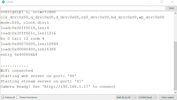
So here My IP is 192.168.1.17, open this address in your browser. And make sure your Smart phone/Laptop and esp32 is connected to same network.
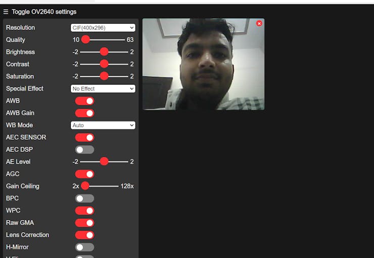
Also this IP can be only used by the Wi-Fi owner, can’t be accessible any other.
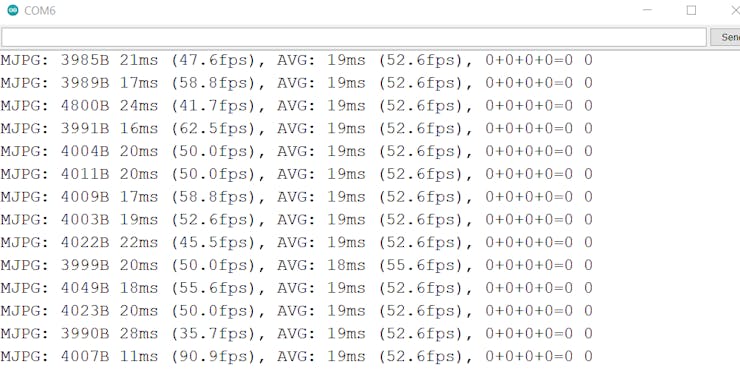
Frame Rates of SPY Wi-Fi camera:
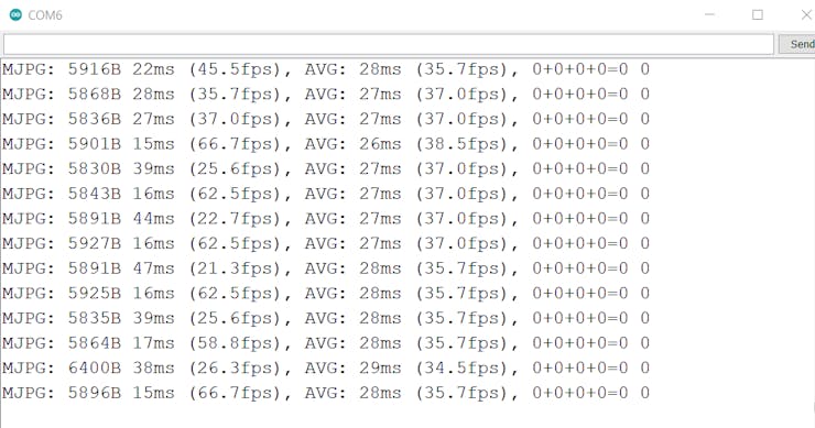
Video quality is very good in CIF and 720p mode, Here is the data of frames per seconds. Bigger the resolution less will be the frames per seconds. But 720p video resolution is good and ready to use for my project:In CIF resolution:
In 720p:
In 1080P:

Making SPY LED:
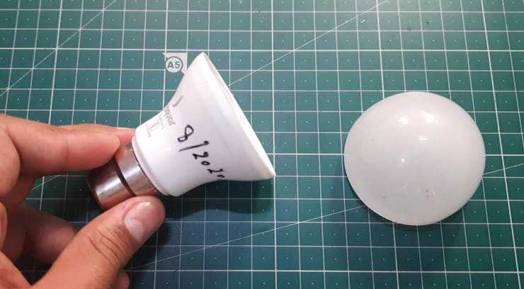
Find a Old Led bulb and remove all the inner circuits, lights and controller. For this module we need a low power and light weight power supply. which can convert 220v to 5volts.
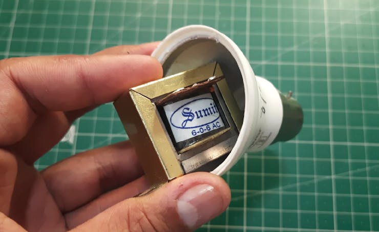
Transformer less power supply:
This is the best power supply for this and nowadays this is very used in IoT bulbs and smart switches. This is compact and use very less components. See full tutorial- How to make Transformer less power supply, circuit diagrams and Gerber files provided.
The Gerber files for this power supply can be downloaded from here. For best prototypes JLCPCB is the only solution, providing 2 layer to 6 layer PCBs (5 pcs in just $2). Checkout JLCPCB from here and get awesome coupons and free gifts on each order.
Combining the circuitry:
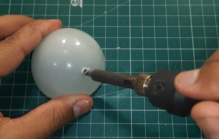
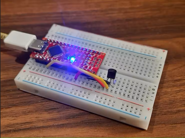
So in the Led first we will install this power supply and then make a hole in diffuser, for camera. Then we will connect all the the things together, give power(5v) to esp32 and we are ready to go.
Installing and Test:

Mount the bulb in the socket and open the same IP address. And you are ready to go with you Anti-theft SPY camera.
VIDEO:
Updates:
In next tutorials we will learn, how to stream over internet. So that we can access our system from anywhere. May be blink IoT will be the solution. So please stay tuned for that. If you are new to my articles then follow us on Hackster, Hackaday and Instructables.
More projects:
1) Arduino based 20Khz Oscilloscope.2) Raspberry Pi Pico based 200khz oscilloscope.