Milliohm meter theory and project
Previously, I made some tutorials regarding current measurements using shunt resistor. Basically, shunt is small known resistance which is in series with the load. And by measuring the voltage drop across the resistor we can find the value of current flowing in the circuit. All credit goes to Ohm’s law: V=IR, by knowing the two of them we can find the 3rd value. But the precision and quality factor also depend on resistance.
We can’t measure resistance below 1 ohms using simple multimeter. That’s why a precision milli-ohm meter is required. Which can measure the values from 0.001ohms to 10ohms. In the last we will also make a PCB shield for better project prototype. In this project we are using a small OLED display of 0.96 inch. This article is brought to you by JLCPCB – Leading PCB manufacturer from CHINA. Register now to JLCPCB and get $54 new user coupons.
Basic Idea:
we will use the same Ohms law to calculate the resistor in milliohms. We have to measure the resistance, by keeping the current constant and measuring the voltage drop finally gives the value of unknown resistance.

To make a supply with constant current here I am using LM317 regulator ic which has a reference voltage of 1.25. You can see the constant current configuration of this IC in datasheet.
Components required:
1) Arduino Nano
2) LM317
3) 10ohms resistor
4) Custom PCB from JLCPCB
5) Power supply
6) OLed display
Circuit diagram:
The screen uses a 4 wire I2C interface with Arduino, 2 wires for the power and 2 for the data. Arduino Nano is required to drive the display panel and to do ohm’s law calculations. We are using a 10ohms resistor between adjust and output pin of the LM317 which gives the current limit of 0.125 amperes. A battery of 9v is required to power the circuit.
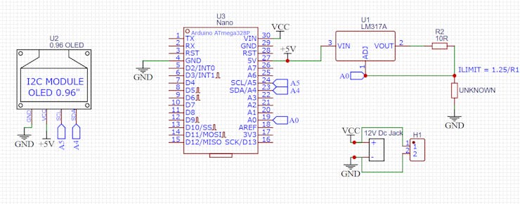
By keeping the current constant at 0.125 amperes and measuring the drop across the unknown resistance. The value goes to ADC of Arduino which then converted into voltage and divided by current. By this method we can measure the small resistance values.
Example:
If the constant current = 0.125 amperes
The voltage drop across the resistance is = 1volt
Then R= V/I = 1/0.125 = 8 ohms, the conversion also applicable to very small values also
PCB designs:
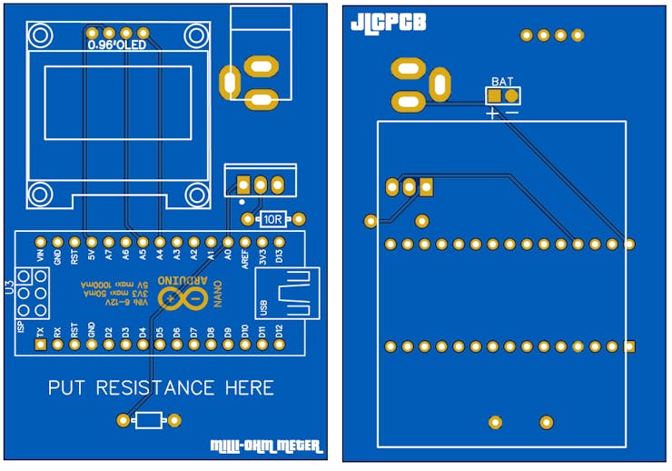
After making the schematics into EasyEDA I converted the circuit into PCB and exported the Gerber files. I made an Arduino shield so that after programming you can plug the components and do measure the small resistance.

I am using pcb service from JLCPCB – CHINA’s Leading PCB manufacturer. JLCPCB is working in the industry for 15 years and the price is just $2 for 5pcs of 2-layer boards. There are many more services you can explore from JLCPCB website like 3d printing, Stencil, PCB prototype, PCBA and SMT assembly. Sign-up now to JLCPCB and get free new user coupons worth $54.
Code:
This program use some common libraries which are available at manage library section under tools menu in Arduino IDE.
#include <Wire.h>
#include <Adafruit_GFX.h>
#include <Adafruit_SSD1306.h>
#define OLED_RESET 1
Adafruit_SSD1306 display(128, 64, &Wire, OLED_RESET);
void setup() {
// initialize serial communication at 9600 bits per second:
Serial.begin(9600);
display.begin(SSD1306_SWITCHCAPVCC, 0x3C);
display.clearDisplay();
}
// the loop routine runs over and over again forever:
void loop() {
// read the input on analog pin 0:
int sensorValue = analogRead(A0);
// Convert the analog reading (which goes from 0 - 1023) to a voltage (0 - 5V):
float voltage = sensorValue * (5.0 / 1024.0);
float Rx = voltage / 0.125;
if (Rx > 36) {
display.clearDisplay();
display.setTextSize(1);
display.setTextColor(WHITE);
display.setCursor(10,10);
display.print( " Out of Range ");
display.display();
delay(1000);
}
if (Rx < 35) {
display.clearDisplay();
display.setTextSize(1);
display.setTextColor(WHITE);
display.setCursor(10,10);
display.print(Rx);
display.setCursor(10,20);
display.print(" Ohm ");
display.display();
delay(1000);
}
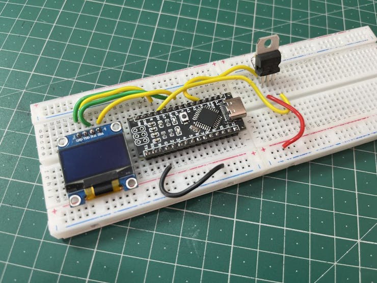
}Demonstration:
After making all the connection I do a test on the breadboard and the circuit is working well. Now it is very easy to measure the small resistors like shunt with more precision. And it can be also used to measure the wirelength using resistor measuring. We will come with a similar project soon.