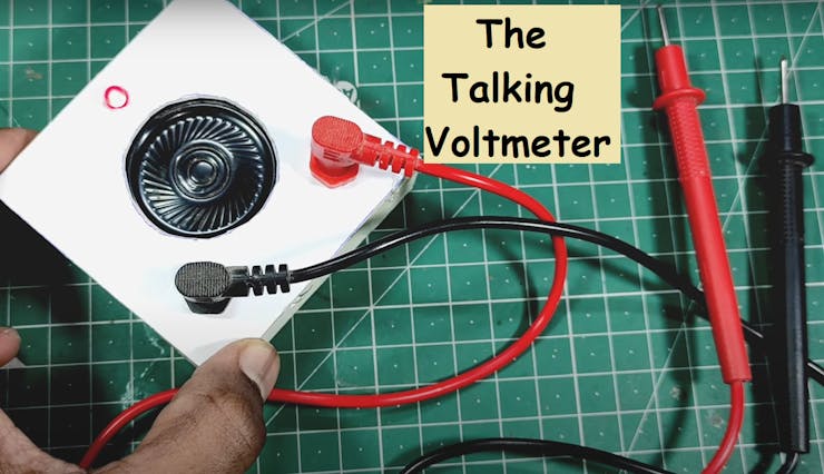
Arduino Based Talking voltmeter
hello guys, today we are going to make a smart talking voltmeter. This one is built on Arduino and gives the reading by speaking itself. This function is cool and attractive because when we are working on circuits, we have to see again and again the readings and then switch the voltmeter leads to measure again the voltage. We will learn how to add supported libraries and where to get them, how talking function of Arduino works, how it reads the voltage and what changes should we have to do in order to increase the range and precision.
Note* For now we are considering a low voltage range from 0-5volts. Which is properly supported by Arduino. To measure high Voltages, we have to add a resistance voltage divider network and change the code accordingly the values of resistance. Every thing is mentioned in the code given below.
Components required:
1) Arduino Nano2) Pam8403 (Class D amplifier)3) 100k Resistor4) Speaker5) 100nf capacitors6) Breadboard and wires
Circuit diagram:
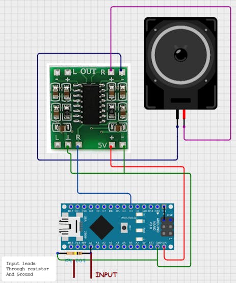
Circuit description:
We are using Arduino Nano in this project which is RISC AVR based 8-bit Microcontroller and here we are using talkie libraries to operate the audio functions. And a class D audio stereo 3W module(PAM8403) to amplify the signal for the speaker. There is a voltage in the digital pin of Arduino which is sensible by the code so a 100k- 1M (High value) resistor is used in parallel of the leads. There should be some voltage drop across the sensor so try to use a bigger value resistor.
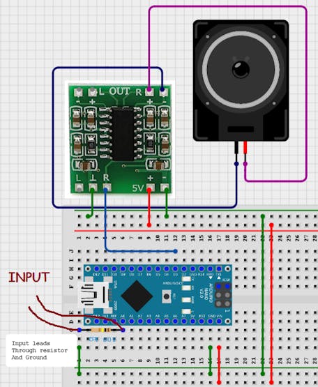
Breadboard schematics:
About Cirkit designer software:
Here is our new schematics designer tool “Cirkit Designer” which is totally free to all and is the most comprehensive breadboard layout tool.Accordingly, I think Cirkit Designer is the best software to make breadboard schematics presentations. It also gives you the ability to view the circuit net diagram and BOM (bill of materials). This is very helpful for presenting yourself well as an electronics student or hobbyist, and the bill of materials helps to estimate project cost and procure parts.
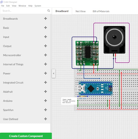
Cirkit Designer is a one-stop-shop desktop application for designing and documenting circuits and electronics projects. With Cirkit Designer, you can lay out realistic circuit diagrams that are linked to a bill-of-materials so that you can seamlessly order the parts to your circuit.Download cirkit designer from HereIn the next release, Cirkit Designer is adding a code IDE with full support for compiling and programming Arduino boards, as well as a library of reference circuit designs (circuit templates including documentation, components and wiring, and code). Cirkit Designer will become the one-stop-shop to help you progress from concept to fully working breadboard prototypes. Simulation will also be added in the future, so that you can test your circuit before buying parts and building anything.
Code:
The code is separated in 3 different parts(2 supported files and one main file). You can Download full code for this project from HERE.
#include <Arduino.h>
#include <Talkie.h>
#include <TalkieUtils.h>
#include <Vocab_Special.h>

#if defined(__AVR__)

#include "ADCUtils.h" // for getVCCVoltage()

#elif defined(ARDUINO_ARCH_SAMD)

// On the Zero and others we switch explicitly to SerialUSB

#define Serial SerialUSB

#endif

#if defined(ESP32)

/*

 * Send serial info over Bluetooth

 * Use the Serial Bluetooth Terminal app and connect to ESP32_Talkie

 */

#include "BluetoothSerial.h"

BluetoothSerial SerialBT;

#define Serial SerialBT // redirect all Serial output to Bluetooth

#endif


/*

 * Voice PWM output pins for different ATmegas:

 *  ATmega328 (Uno and Nano): non inverted at pin 3, inverted at pin 11.

 *  ATmega2560: non inverted at pin 6, inverted at pin 7.

 *  ATmega32U4 (Leonardo): non inverted at pin 10, inverted at pin 9.

 *  ATmega32U4 (CircuitPlaygound): only non inverted at pin 5.

 *

 *  As default both inverted and not inverted outputs are enabled to increase volume if speaker is attached between them.

 *  Use Talkie Voice(true, false); if you only need not inverted pin or if you want to use SPI on ATmega328 which needs pin 11.

 *

 *  The outputs can drive headphones directly, or add a simple audio amplifier to drive a loudspeaker.

 */

Talkie Voice;

//Talkie Voice(true, false);

void setup() {

//    pinMode(LED_BUILTIN, OUTPUT);


#if defined(ESP32) && defined(Serial)

    Serial.begin("ESP32_Talkie", false);

#else

    Serial.begin(115200);

#endif

#if defined(__AVR_ATmega32U4__) || defined(SERIAL_USB) || defined(SERIAL_PORT_USBVIRTUAL)  || defined(ARDUINO_attiny3217) || (defined (USBCON) && defined(USBD_USE_CDC))

    delay(4000); // To be able to connect Serial monitor after reset or power up and before first print out. Do not wait for an attached Serial Monitor!

#endif

    // Just to know which program is running on my Arduino

    Serial.println(F("START " __FILE__ " from " __DATE__ "\r\nUsing library version " VERSION_TALKIE));


#if defined(TEENSYDUINO)

    pinMode(5, OUTPUT);

    digitalWrite(5, HIGH); //Enable Amplified PROP shield

#elif defined(ARDUINO_ARCH_SAMD)

    analogReadResolution(12);

#endif

    Serial.print(F("Voice queue size is: "));

    Serial.flush();

    Serial.println(Voice.sayQ(spPAUSE1)); // this initializes the queue and the hardware

#if defined(ARDUINO_ARCH_SAMD)

    Serial.println(F("Read voltage at pin A1"));

#else

    Serial.println(F("Read voltage at pin A0"));

#endif

   Serial.print(F("Speech output at pin "));

#if defined(ARDUINO_ARCH_STM32)

    Serial.println("PA3"); // the internal pin numbers are crazy for the STM32 Boards library

#elif defined(ARDUINO_ARCH_SAMD)

    Serial.println("A0"); // DAC0 is at PIN 14/A0

#else

    Serial.print(Voice.NonInvertedOutputPin);

#endif


    if (Voice.InvertedOutputPin && Voice.InvertedOutputPin != TALKIE_USE_PIN_FLAG) {

        Serial.print(F(" and inverted output at pin "));

        Serial.print(Voice.InvertedOutputPin);

    }

    Serial.println();

    Serial.flush();

}

void loop() {

#if defined(__AVR__)

    float tVCCVoltage = getVCCVoltage();

    Serial.print(tVCCVoltage);

    Serial.println(" volt VCC");


    int tVoltage = analogRead(A0) * tVCCVoltage / 1.023;

#elif defined(ESP32)

    int tVoltage = analogRead(A0) * 3.3 / 4.096;

#elif defined(__STM32F1__) || defined(ARDUINO_ARCH_STM32F1)

    int tVoltage = analogRead(0) * 3.3 / 4.096;

#elif defined(ARDUINO_ARCH_SAMD)

    int tVoltage = analogRead(A1) * 3.3 / 4.096; // A0 is DAC output

#else

    int tVoltage = analogRead(0) * 3.3 / 1.023;

#endif


    Serial.print(tVoltage);

    Serial.println(" mV input");

    Serial.flush();

//    sayQVoltageMilliVolts(&Voice, tVoltage);

    float tVoltageFloat = tVoltage / 1000.0;

    sayQVoltageVolts(&Voice, tVoltageFloat);

    // Using .say() here is another way to block the sketch here and wait for end of speech as you can easily see in the source code of say().

    Voice.sayQ(spPAUSE1);

    while (Voice.isTalking()) {

        ;

    }

    delay(200);

}
this code is designed for more than one microcontroller board, so if are using any other supported MCU, the Pin mapping will be:
* Platform     Normal      Inverted    8kHz timer  PWM timer
* -------------------------------------------------------
* AVR          3           11          1           2
* ATmega2560   6/PH3       7/PH4       1           4
* Leonardo     9/PB5       10/PB6      1           4
* ProMicro     5/PC6       %           1           4 - or Adafruit Circuit Playground Classic
* Esplora      6/PD7       %           1           4
* Zero (SAMD)  A0          %           TC5         DAC0
* ESP32        25          %           hw_timer_t  DAC0
* BluePill     3           %           timer3      analogWrite Roger Clarks core
* BluePill     PA3         %           timer4      analogWrite STM core
* Teensy       12/14721    %         IntervalTimer analogWrite
*  As default both inverted and not inverted outputs are enabled for AVR to increase volume if speaker is attached between them.
*  Use Talkie Voice(true, false); if you only need not inverted pin or if you want to use SPI on ATmega328 which needs pin 11.
*  The outputs can drive headphones directly, or add a simple audio amplifier to drive a loudspeaker.
Working:
Through Analog functions of the microcontroller, we can read the voltage using this. But without a resistor divider network, only a small voltage can be measured (In the range of microcontroller).Using an Arduino to measure voltages is relatively simple. Inside the Arduino, there are multiple analog input pins connecting to an analog-to-digital converter (ADC). The Arduino ADC is a ten-bit converter, and the output value ranges from 0 to 1023. We will obtain this value using the analogRead() function.
Video:
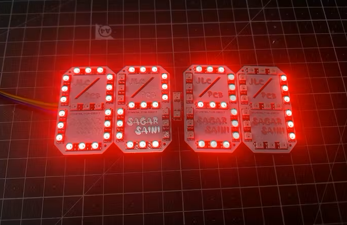
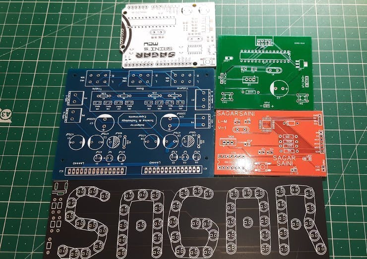
PCB designs:
Download all the required files(Gerber, code, circuit) for this project from HERE.

JLCPCB:
JLCPCB is the one of the most popular PCB makers. Price is just $2 for 2, 4 and 6 layer PCB. They just launched new purple solder mask, aluminum Pcb and 3d printing service in very low cost. Pcb quality is not compromised at any cost. Check them out right now from Here.
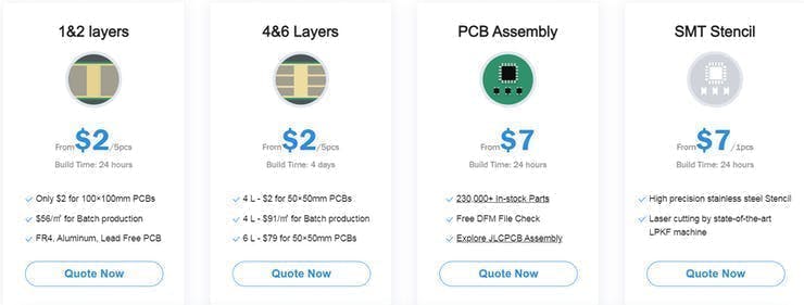
JLCPCB Is also providing new user coupons and sign-up rewards of up to $30. So, check them out from here. Register using this link to get Free PCB assembly service coupons. Get your 2 layer to 6-layer PCB’s just in $2, stencil and PCB assembly service in just $7.For PC: https://jlcpcb.com/SSRFor mobile phone: http://m.jlcpcb.com/ssi
Updates:
In the next updates I will try to update this voltmeter into a combination of ohmmeter and ammeter. So that it can measure resistance, current and voltage with different modes in a single multi-meter.
More projects:
1) How to make Arduino Uno clone board. 2) How to program Arduino Using Smart Phone.3) Arduino Nano clone board problems and solutions.4) How to make Inductance Meter Using Arduino.5) Raspberry Pi- PICO Oscilloscope.6) Arduino based Oscilloscope
Think you enjoy my work, stay tuned. Follow us on Instagram (sagar_saini_7294) and hackaday.please support us- No donations, just follow and leave a comment.