

Neopixel RGB Ring JLCPCB Smt Service
Hello guys, today we are going to make this RGB ring using Neo pixel led’s. we will learn, something new about Neo pixel, how to operate them, how to show different animations and how to make your own RGB neo pixel ring. In last we will control them using Arduino Nano board and make some cool stuff to show by combining all the rings.
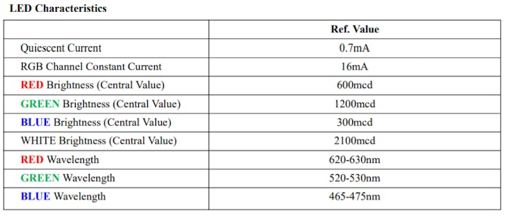
Led specifications:
Here we are using 5mm*5mm WS2812 RGB addressable led’s. These led have a special inbuild chip which give them address to glow. Using MCU we can generate an analog value between 0-255 in which is also defined in the code as 0- brightness.
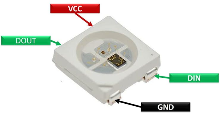
Now take 3 different value like (0,125,255) the first value represent the intensity of red color, second & third represent green and blue respectively. By changing the values we can represent different color scheme.
This mini Led can be operated in the voltage of range of 3.3 to 5 volts without any external resistor. Although we can control the brightness through the code.
Components required:
1) Arduino Nano2) Custom PCB’s3) Wires and all4) Soldering equipments
Making of an RGB ring:
I want to make a large one, which is not available in market, so JLCPCB comes to my mind and then I think to go with SMT service. So I made a schematics using EasyEDA and choose a proper component which is cheap and in stock.
Circuit diagram:
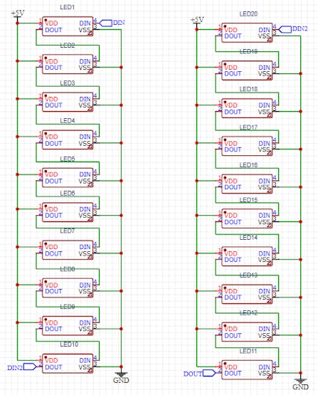
Circuit description:
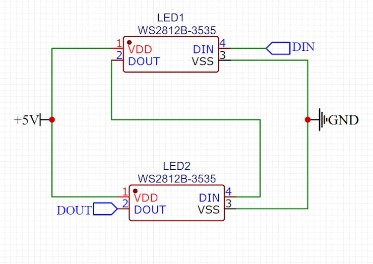
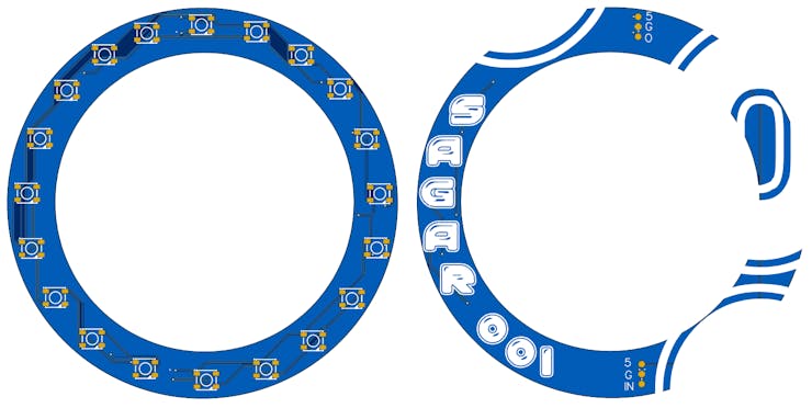
I connected all the LED’s in parallel and made the all the data connection in series. Keeping an eye on input and output, some headers are placed accordingly. Making all the power connection in parallel is easy and can be power directly through microcontroller line. One panel/ring has 20 Led’s and in this manner you can connect them all.
Code:
1) Download all the libraries, link is given below or include them through manage libraries option under the tools menu in Arduino IDE.
#include <Adafruit_NeoPixel.h>
#ifdef __AVR__
 #include <avr/power.h> // Required for 16 MHz Adafruit Trinket
#endif
2) Choose the Arduino digital pin from D2 to D13 and then the total number of LED’s.
#define LED_PIN    6

// How many NeoPixels are attached to the Arduino?
#define LED_COUNT 60
3) See the datasheet of LED used in project and uncomment the line, In most case it will work on this:
// Declare our NeoPixel strip object:
Adafruit_NeoPixel strip(LED_COUNT, LED_PIN, NEO_GRB + NEO_KHZ800);
// Argument 1 = Number of pixels in NeoPixel strip
// Argument 2 = Arduino pin number (most are valid)
// Argument 3 = Pixel type flags, add together as needed:
//   NEO_KHZ800  800 KHz bitstream (most NeoPixel products w/WS2812 LEDs)
//   NEO_KHZ400  400 KHz (classic 'v1' (not v2) FLORA pixels, WS2811 drivers)
//   NEO_GRB     Pixels are wired for GRB bitstream (most NeoPixel products)
//   NEO_RGB     Pixels are wired for RGB bitstream (v1 FLORA pixels, not v2)
//   NEO_RGBW    Pixels are wired for RGBW bitstream (NeoPixel RGBW products)
4) Initialize the Led’s and set the brightness from 0 to 255. More the brightness more the led will draw the current.
strip.begin();           // INITIALIZE NeoPixel strip object (REQUIRED)
  strip.show();            // Turn OFF all pixels ASAP
  strip.setBrightness(50); // Set BRIGHTNESS to about 1/5 (max = 255)
}
5) In the loop section there are 3 piece of code, you can change them increase/ decrease the time of effect and speed.
// Fill along the length of the strip in various colors...
  colorWipe(strip.Color(255,   0,   0), 50); // Red
  colorWipe(strip.Color(  0, 255,   0), 50); // Green
  colorWipe(strip.Color(  0,   0, 255), 50); // Blue

  // Do a theater marquee effect in various colors...
  theaterChase(strip.Color(127, 127, 127), 50); // White, half brightness
  theaterChase(strip.Color(127,   0,   0), 50); // Red, half brightness
  theaterChase(strip.Color(  0,   0, 127), 50); // Blue, half brightness

  rainbow(10);             // Flowing rainbow cycle along the whole strip
  theaterChaseRainbow(50); // Rainbow-enhanced theaterChase variant
}
6) In the code (127, 127, 127), 50) these number will define the color and the brightness id defined by (127, 127, 127), 50) this 50. The code is fully flexible and good to go. Try other different effects/code from the library <Adafruit_NeoPixel.h>
Working code:
// A basic everyday NeoPixel strip test program.
// NEOPIXEL BEST PRACTICES for most reliable operation:
// - Add 1000 uF CAPACITOR between NeoPixel strip's + and - connections.
// - MINIMIZE WIRING LENGTH between microcontroller board and first pixel.
// - NeoPixel strip's DATA-IN should pass through a 300-500 OHM RESISTOR.
// - AVOID connecting NeoPixels on a LIVE CIRCUIT. If you must, ALWAYS
// connect GROUND (-) first, then +, then data.
// - When using a 3.3V microcontroller with a 5V-powered NeoPixel strip,
// a LOGIC-LEVEL CONVERTER on the data line is STRONGLY RECOMMENDED.
// (Skipping these may work OK on your workbench but can fail in the field)
#include <Adafruit_NeoPixel.h>
#ifdef __AVR__
#include <avr/power.h> // Required for 16 MHz Adafruit Trinket
#endif
// Which pin on the Arduino is connected to the NeoPixels?
// On a Trinket or Gemma we suggest changing this to 1:
#define LED_PIN 6
// How many NeoPixels are attached to the Arduino?
#define LED_COUNT 60
// Declare our NeoPixel strip object:
Adafruit_NeoPixel strip(LED_COUNT, LED_PIN, NEO_GRB + NEO_KHZ800);
// Argument 1 = Number of pixels in NeoPixel strip
// Argument 2 = Arduino pin number (most are valid)
// Argument 3 = Pixel type flags, add together as needed:
// NEO_KHZ800 800 KHz bitstream (most NeoPixel products w/WS2812 LEDs)
// NEO_KHZ400 400 KHz (classic 'v1' (not v2) FLORA pixels, WS2811 drivers)
// NEO_GRB Pixels are wired for GRB bitstream (most NeoPixel products)
// NEO_RGB Pixels are wired for RGB bitstream (v1 FLORA pixels, not v2)
// NEO_RGBW Pixels are wired for RGBW bitstream (NeoPixel RGBW products)
// setup() function -- runs once at startup --------------------------------
void setup() {
// These lines are specifically to support the Adafruit Trinket 5V 16 MHz.
// Any other board, you can remove this part (but no harm leaving it):
#if defined(__AVR_ATtiny85__) && (F_CPU == 16000000)
clock_prescale_set(clock_div_1);
#endif
// END of Trinket-specific code.
strip.begin(); // INITIALIZE NeoPixel strip object (REQUIRED)
strip.show(); // Turn OFF all pixels ASAP
strip.setBrightness(50); // Set BRIGHTNESS to about 1/5 (max = 255)
}
// loop() function -- runs repeatedly as long as board is on ---------------
void loop() {
// Fill along the length of the strip in various colors...
colorWipe(strip.Color(255, 0, 0), 50); // Red
colorWipe(strip.Color( 0, 255, 0), 50); // Green
colorWipe(strip.Color( 0, 0, 255), 50); // Blue
// Do a theater marquee effect in various colors...
theaterChase(strip.Color(127, 127, 127), 50); // White, half brightness
theaterChase(strip.Color(127, 0, 0), 50); // Red, half brightness
theaterChase(strip.Color( 0, 0, 127), 50); // Blue, half brightness
rainbow(10); // Flowing rainbow cycle along the whole strip
theaterChaseRainbow(50); // Rainbow-enhanced theaterChase variant
}
// Some functions of our own for creating animated effects -----------------
// Fill strip pixels one after another with a color. Strip is NOT cleared
// first; anything there will be covered pixel by pixel. Pass in color
// (as a single 'packed' 32-bit value, which you can get by calling
// strip.Color(red, green, blue) as shown in the loop() function above),
// and a delay time (in milliseconds) between pixels.
void colorWipe(uint32_t color, int wait) {
for(int i=0; i<strip.numPixels(); i++) { // For each pixel in strip...
strip.setPixelColor(i, color); // Set pixel's color (in RAM)
strip.show(); // Update strip to match
delay(wait); // Pause for a moment
}
}
// Theater-marquee-style chasing lights. Pass in a color (32-bit value,
// a la strip.Color(r,g,b) as mentioned above), and a delay time (in ms)
// between frames.
void theaterChase(uint32_t color, int wait) {
for(int a=0; a<10; a++) { // Repeat 10 times...
for(int b=0; b<3; b++) { // 'b' counts from 0 to 2...
strip.clear(); // Set all pixels in RAM to 0 (off)
// 'c' counts up from 'b' to end of strip in steps of 3...
for(int c=b; c<strip.numPixels(); c += 3) {
strip.setPixelColor(c, color); // Set pixel 'c' to value 'color'
}
strip.show(); // Update strip with new contents
delay(wait); // Pause for a moment
}
}
}
// Rainbow cycle along whole strip. Pass delay time (in ms) between frames.
void rainbow(int wait) {
// Hue of first pixel runs 5 complete loops through the color wheel.
// Color wheel has a range of 65536 but it's OK if we roll over, so
// just count from 0 to 5*65536. Adding 256 to firstPixelHue each time
// means we'll make 5*65536/256 = 1280 passes through this outer loop:
for(long firstPixelHue = 0; firstPixelHue < 5*65536; firstPixelHue += 256) {
for(int i=0; i<strip.numPixels(); i++) { // For each pixel in strip...
// Offset pixel hue by an amount to make one full revolution of the
// color wheel (range of 65536) along the length of the strip
// (strip.numPixels() steps):
int pixelHue = firstPixelHue + (i * 65536L / strip.numPixels());
// strip.ColorHSV() can take 1 or 3 arguments: a hue (0 to 65535) or
// optionally add saturation and value (brightness) (each 0 to 255).
// Here we're using just the single-argument hue variant. The result
// is passed through strip.gamma32() to provide 'truer' colors
// before assigning to each pixel:
strip.setPixelColor(i, strip.gamma32(strip.ColorHSV(pixelHue)));
}
strip.show(); // Update strip with new contents
delay(wait); // Pause for a moment
}
}
// Rainbow-enhanced theater marquee. Pass delay time (in ms) between frames.
void theaterChaseRainbow(int wait) {
int firstPixelHue = 0; // First pixel starts at red (hue 0)
for(int a=0; a<30; a++) { // Repeat 30 times...
for(int b=0; b<3; b++) { // 'b' counts from 0 to 2...
strip.clear(); // Set all pixels in RAM to 0 (off)
// 'c' counts up from 'b' to end of strip in increments of 3...
for(int c=b; c<strip.numPixels(); c += 3) {
// hue of pixel 'c' is offset by an amount to make one full
// revolution of the color wheel (range 65536) along the length
// of the strip (strip.numPixels() steps):
int hue = firstPixelHue + c * 65536L / strip.numPixels();
uint32_t color = strip.gamma32(strip.ColorHSV(hue)); // hue -> RGB
strip.setPixelColor(c, color); // Set pixel 'c' to value 'color'
}
strip.show(); // Update strip with new contents
delay(wait); // Pause for a moment
firstPixelHue += 65536 / 90; // One cycle of color wheel over 90 frames
}
}
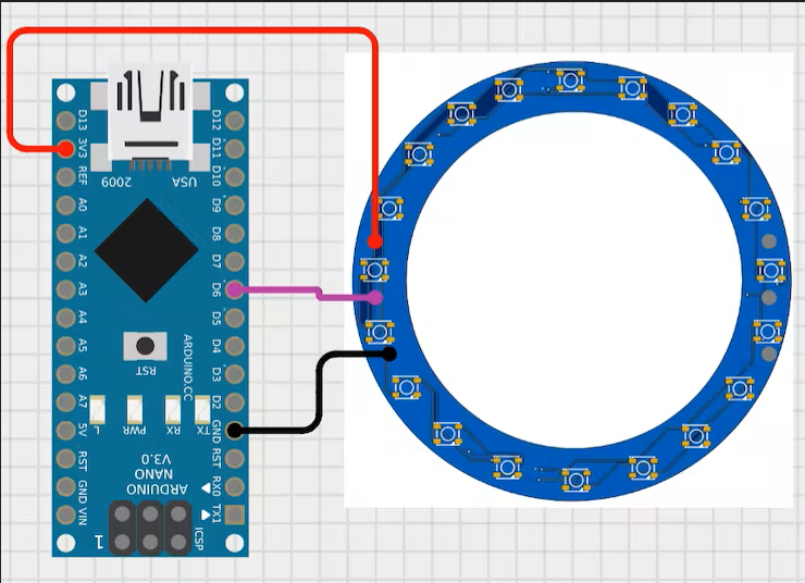
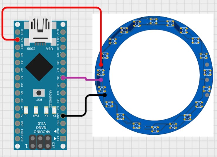
}Arduino circuit:
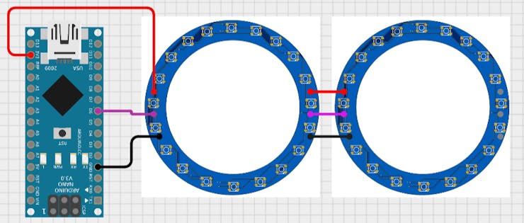
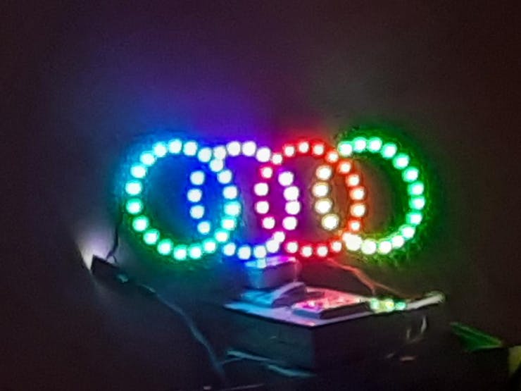
As mentioned in the code, connect data line to D6. connect the power +5v and ground. To join 2 or more RGB rings together we can do these connection and the code will be modified according to the number of led’s as described above.
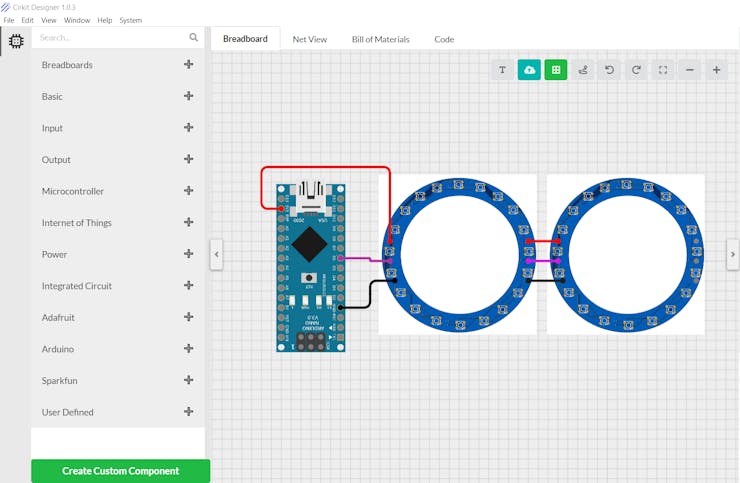
About Cirkit designer software:
Here is our new schematics designer tool “Cirkit Designer” which is totally free to all and is the most comprehensive breadboard layout tool.Accordingly, I think Cirkit Designer is the best software to make breadboard schematics presentations. It also gives you the ability to view the circuit net diagram and BOM (bill of materials). This is very helpful for presenting yourself well as an electronics student or hobbyist, and the bill of materials helps to estimate project cost and procure parts.
Cirkit Designer is a one-stop-shop desktop application for designing and documenting circuits and electronics projects. With Cirkit Designer, you can lay out realistic circuit diagrams that are linked to a bill-of-materials so that you can seamlessly order the parts to your circuit.Download cirkit designer from HereIn the next release, Cirkit Designer is adding a code IDE with full support for compiling and programming Arduino boards, as well as a library of reference circuit designs (circuit templates including documentation, components and wiring, and code). Cirkit Designer will become the one-stop-shop to help you progress from concept to fully working breadboard prototypes. Simulation will also be added in the future, so that you can test your circuit before buying parts and building anything.
PCB design:
Download all the material, Gerber, circuit and supported libraries from here.
Video:
Troubleshooting:
1) Din is always connected to Dout in series with on e another, if connected in opposite or disconnected from anywhere whole setup stops working.2) Make sure all the connections are properly soldered, dry soldering will cause change in data value and color.3) Don’t heat the PCB too much, while Soldering and keep the temperature on 300*c.
My RGB ring:
JLCPCB:
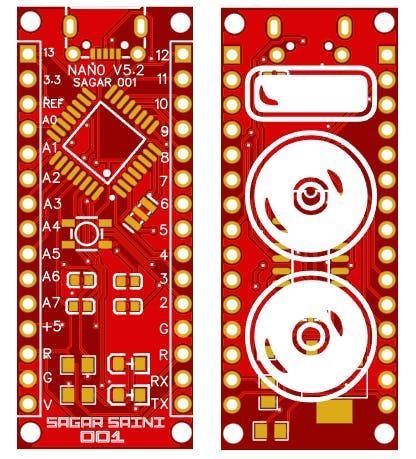
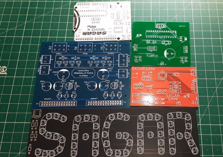
I have my own Arduino boards because of JLCPCB to program them/troubleshoot them and learn from them. If you want to make your own board, the JLCPCB SMT service can be the solution.
JLCPCB is the one of the most popular PCB makers. Price is just $2 for 2, 4 and 6 layer PCB. They just launched new purple solder mask, aluminum Pcb and 3d printing service in very low cost. Pcb quality is not compromised at any cost. Check them out right now from Here.
JLCPCB Is also providing new user coupons and sign-up rewards of up to $30. So, check them out from here. Register using this link to get Free PCB assembly service coupons. Get your 2 layer to 6-layer PCB’s just in $2, stencil and PCB assembly service in just $7.For PC: https://jlcpcb.com/SSRFor mobile phone: http://m.jlcpcb.com/ssiHere are some exciting projects, which you may like:
Here are some exciting projects, which you may like:
1) How to make Arduino Uno clone board. 2) How to program Arduino Using Smart Phone.3) Arduino Nano clone board problems and solutions.4) How to make Inductance Meter Using Arduino.5) Raspberry Pi- PICO Oscilloscope.
***My RGB clock project using Nodemcu ESP8266Think you enjoyed my work, stay tuned. Follow us on Instagram (sagar_saini_7294) and hackaday.please support us- No donations, just follow and leave a comment.


