Making of a 200watts Audio Amplifier
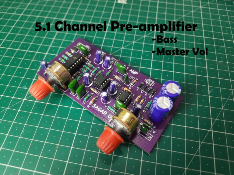
In last tutorial, we made a preamplifier for 5.1 party boom box. Now it is the time for the amplifier. We will design the compatible 5.1 amplifier for this, as mentioned earlier to drive 100watt subwoofer and 4x 25watt speakers. TDA series integrated circuits are best for this purpose that provides a high-fidelity output stage.

After that we will design a PCB in EasyEda and order it from JLCPCB. JLCPCB provides the prototype PCB service in just $2 for 5pcs. All the setup can be powered using a single transformer of 36volts @5amps.
Selection of components:
There are some dedicated audio integrated from ST microelectronics which can fulfil the requirements directly. For the subwoofer either we can use TDA7294 class AB (100W) or LM3886 IC (68W). And for the speakers we can use TDA7265 or TDA7377.
Subwoofer IC:
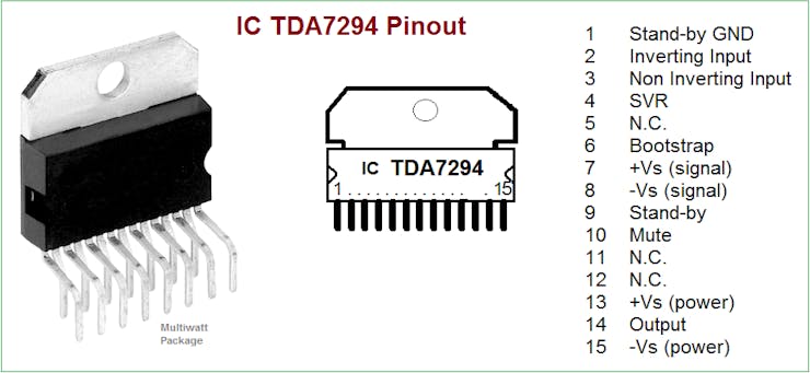
In this circuit due to the cost and availability the TDA7294 100w is the best solution. Hence the datasheet refers: The TDA7294 is a monolithic integrated circuit in Multiwatt15 package, intended for use as audio class AB amplifier in Hi-Fi field applications (Home Stereo, self-powered loudspeakers, Top-class TV). Thanks to the wide voltage range and to the high out current capability it is able to supply the highest power into both 4 Ω and 8 Ω loads even in presence of poor supply regulation, with high supply voltage rejection. The built-in muting function with turn on delay simplifies the remote operation avoiding switching on-off noises.
Features
· Very high operating voltage range (± 40 V)
· DMOS power stage
· High output power (up to 100 W music power)
· Muting/stand-by functions
· No switch on/off noise
· No Bouche rot cells
· Very low distortion
· Very low noise
· Short circuit protection
· Thermal shutdown
Speaker IC:
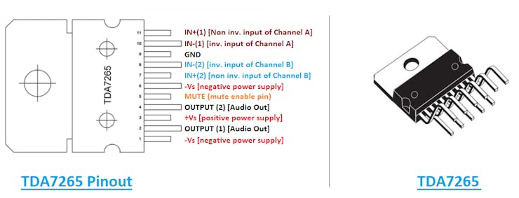
The TDA7265 is class AB dual Audio power amplifier assembled in the Multi watt package, specially designed for high quality sound application as Hi-Fi music centers and stereo TV sets.
Features:
· WIDE SUPPLY VOLTAGE RANGE (UP TO ±25V ABS MAX.)
· SPLIT SUPPLY HIGH OUTPUT POWER 25 + 25W @ THD =10%, RL = 8Ω, VS = +20V
· NO POP AT TURN-ON/OFF MUTE (POP FREE)
· STAND-BY FEATURE (LOW Iq)
· SHORT CIRCUIT PROTECTION
· THERMAL OVERLOAD PROTECTION
Components Required:
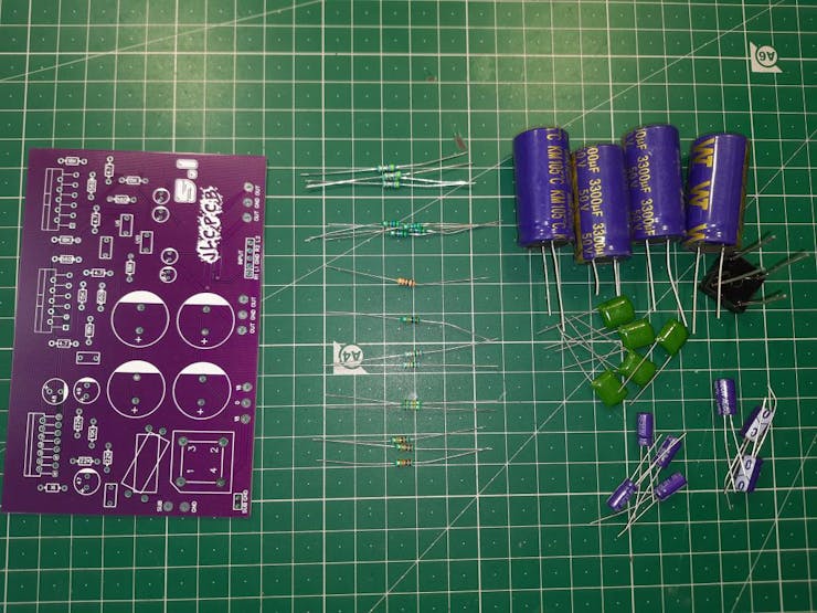
1) TDA7294
2) TDA7265
3) 100nf and 1nf polyester film capacitors
4) 4.7uf, 47uf, 100uf, 3500uf electrolytic capacitors
5) 4.7ohm, 560ohm, 1k, 10k, 15k, 18k and 22k resistors (¼ watts)
6) 6amp rectifier
7) Pin headers
8) Custom PCB
Circuit Diagram:
After looking into the datasheet, I found some application circuits of the IC but some of them are really complicated or designed according the required gain. That’s why I designed my own circuit in Easyeda and then turned the schematics into the PCB.
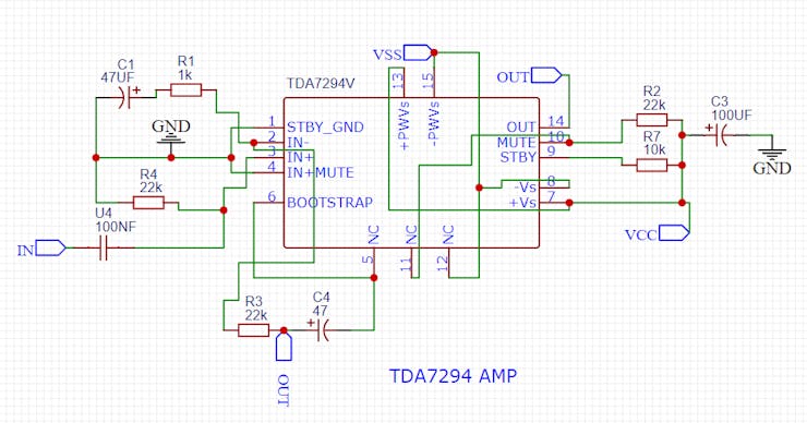
The circuit is designed in the manner than 7265 pair can output the amplifier audio signal for all the four speakers and 7294 is used in the mono mode to provide a massive output of 100watts for subwoofer. The maximum power draw is 200watts which can be given to the amplifier through a linear power supply. Both the audio IC need dual channel power supply in this case we are using a 18-0-18 transformer with onboard rectifier and filtration circuit.
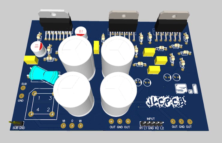
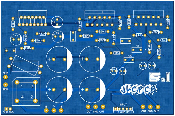
PCB designs:
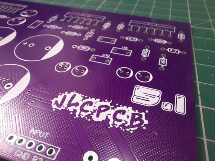
A total of 3 audio integrated circuits are place in one alignment to fix the heat dissipator after assembly. Here I used purple color solder mask with 1.6mm thickness and Hasl with lead finishing.
If you want to use the same designs as mine then download them from here. Go to JLCPCB > quote now > Upload your Gerber file > choose all the parameters like quantity, thickness, solder mask color and type of finishing > Add to cart and make payment > Get your PCBs at home in just 7 days after dispatching.
PCB details:
This is FR4 material which is quite strong and heavy for PCB manufacturing. I updated the designed rule of normal track width to 0.45mm with 0.152 clearance and power lanes, Subwoofer tracks to 1.8mm with a clearance of 0.160mm. It is dual layered PCB because of so many tracks and to avoid cross connections.
You can order the same PCB in just $2 using JLCPCB prototype PCB service and if you sign-up using this link you will get coupons of worth $54 to place your orders on JLCPCB.
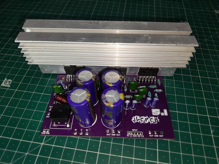
Assembly:
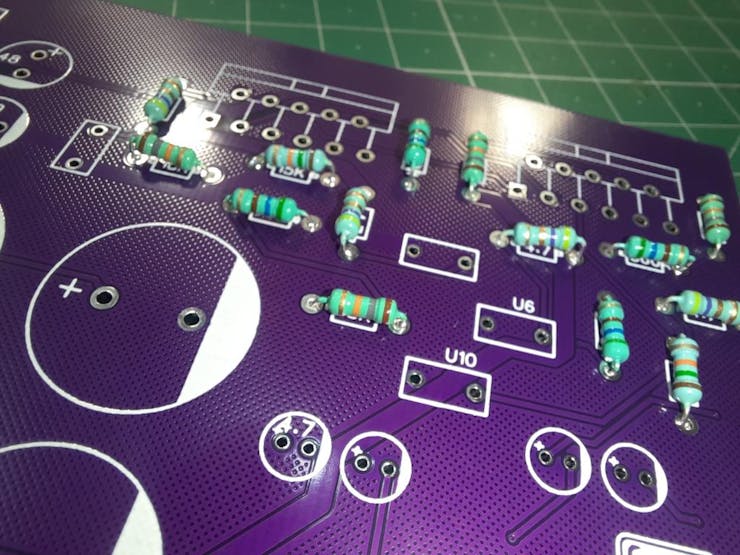
First, I soldered all the mini components like resistors and small electrolytic capacitors. I always recommend to solder the power section in last because of the big filtration capacitors.
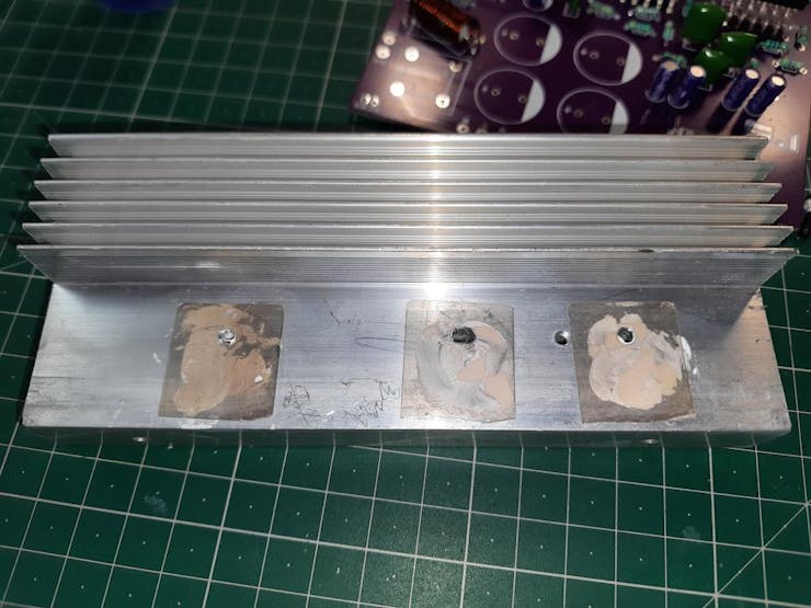
Then I solder all the audio IC and mount a heatsink on it by placing a mica sheet and applying some heat dissipation paste. A CPU fan can be further attached to remove the excessive heat.
Connection Diagram:
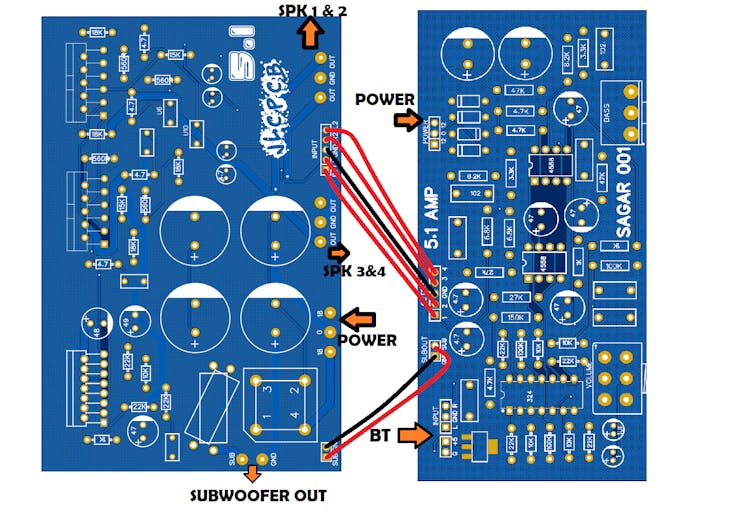
Working:
Then I made all the connections to it with power supply, preamplifier and speakers. The audio quality is really very fantastic. Bass feel realistic and if your Bluetooth support DOLBY or any other surround sound it helps you a lot to create the best sound effect ever. You can listen to the bass and speaker audio quality in the video.