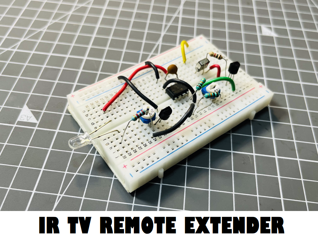
IR Remote Extender and Repeater using 555
Previously I made an IR remote block, which can block or jam the signal from an IR remote to any device like radio or TV. But sometime case is to increase the range of remote. If you are inside a room and want to operate in other place or in second room then the concept of range extender comes. Usually most of the IR remotes use NEC based protocol which can be decoded via TSOP and can be converted into digital signal.
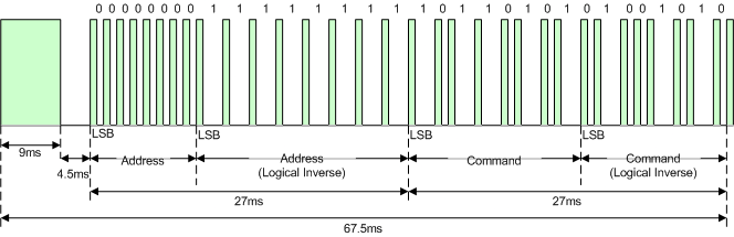
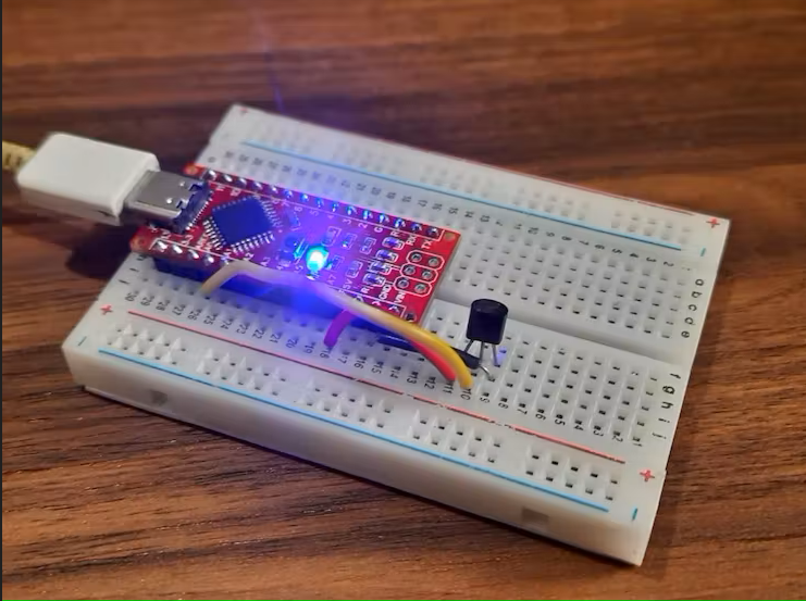
A basic NEC signal contain a starting bit, ending bit and data in between and all of these is carried on a carrier square wave of 38-40Khz. Your device may have any frequency range between 38 to 40Khz. Then the signal is emitted via an IR led. You cannot see the infrared signal with bare eyes to verify the operation the violet – Red color light can be seen in a video camera or phone camera.

JLCPCB is a leading PCB prototype and assembly service provider. With over 14 years of experience, JLCPCB offers high-quality, reliable and affordable PCB services to customers all over the world. Their online platform allows you to easily upload your PCB design files, get an instant quote, and place your order. Get you PCB now in low prices 5pcs of 2-layer PCB starting from just $2. Register using this link to JLCPCB and get free coupons of worth $54.
TSOP1738 Sensor:
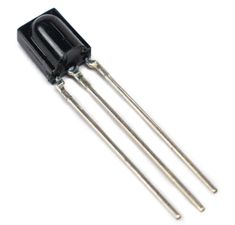
This is the IR receiver decoder and demodulator in a single package. TSOP is the all-in-one dude which can decode the received signal digitally and demodulate it from the carrier wave. This signal now contains only high and low values. By a simple IR receiver, we cannot construct back the original signal that’s why here TSOP is taken in use. This sensor works on a logic voltage and the output is always logic high and pulled to low whenever the IR signal is detected.
Sending the IR signal again:
Now to send the IR signal to receiver in order to extend the range we need a modulator again and then we can superimpose the signal on that and transmit it to next receiver. We need a proper external clock of 38-40khz which can be made using IC 555 and the operations continues. Here we will use the control pin of the 555 to get the control over output and need some switching transistors. In this way 555 works as a modulator and we get the signal on an adjustable carrier. Which can be tuned then to any dedicated receiver.
Components required:

- NE555
- NPN transistor 2n3904
- 1k, 10K resistor
- 10k variable resistor
- 10nf, 100nf ceramic capacitor
- TSOP1738
- IR transmitter LED
- Custom PCB from JLCPCB
- 5V power source
Circuit diagram:
The circuit diagram is quite simple, first we need to set the 555 in astable mode which can produce a fixed clock of 38-40Khz. For tunning the output, we can use a variable resistor in parallel with second discharging resistor. To calculate any fixed value from 555, use this online calculator.

By connecting the control voltage to the transistor. Threshold comparator of the 555 is always gives a high output. And whenever the IR signal is detected the operation is done in a successful manner. The operation can be understood as whenever there is no signal condition the output of 555 is low and trigged as per IR signal this will produce the exact replica of the signal on the output which then converted to logic high values via 3904 transistor and transmitted via the IR LED.

In this way a logic voltage is operated or changed from one to other logic, transistor switches are basic and very crucial unit of this circuit. And these transistor can hold a maximum of 100mA of current any short circuit may damage the transistor directly. In addition to increase the overall signal strength multiple LEDS can be connected together in parallel combination. Which also increase the range and coverage area. All the circuity can be operated with 5v 500mA power supply or battery.
Gerber files and PCB designs:
To design the schematics, I am using EasyEDA then I made the Gerber files from this. You can use my Gerber files to order the same PCB or to repeat the project in other way the above given circuit can be modified to some extent.

For the PCB manufacturing I am using JLCPCB prototyping service, JLCPCB offer a very high-quality PCB in very low prices. They are offering 5pcs of 2-6 Layer PCB in just $2. Sign-up now using this link and get worth $54 new user discount coupons for next order.
Working and testing:

You can observe the signal on DSO, replica of signal is the output through the 555 with the carrier frequency in it. The carrier can be tuned by using an y frequency meter or oscilloscope keeping the IC 555 in astable mode.
Then I made the testing bench in which the receiver and transmitter is far apart and obstacle between them. Direct communication of IR remote to the receiver is not possible and extender play a very great role. See the full video and all the Circuit diagram, Gerber files can be downloaded from here.
PCB ordering procedure:
Download the Gerber files from here.

Upload them to JLCPCB and select the order quality, color, finishing type.

Then add the PCB into cart.

Checkout via any online payment method. Don’t forget to redeem those free coupons.

Get your PCB prototypes just ready in 7 days.