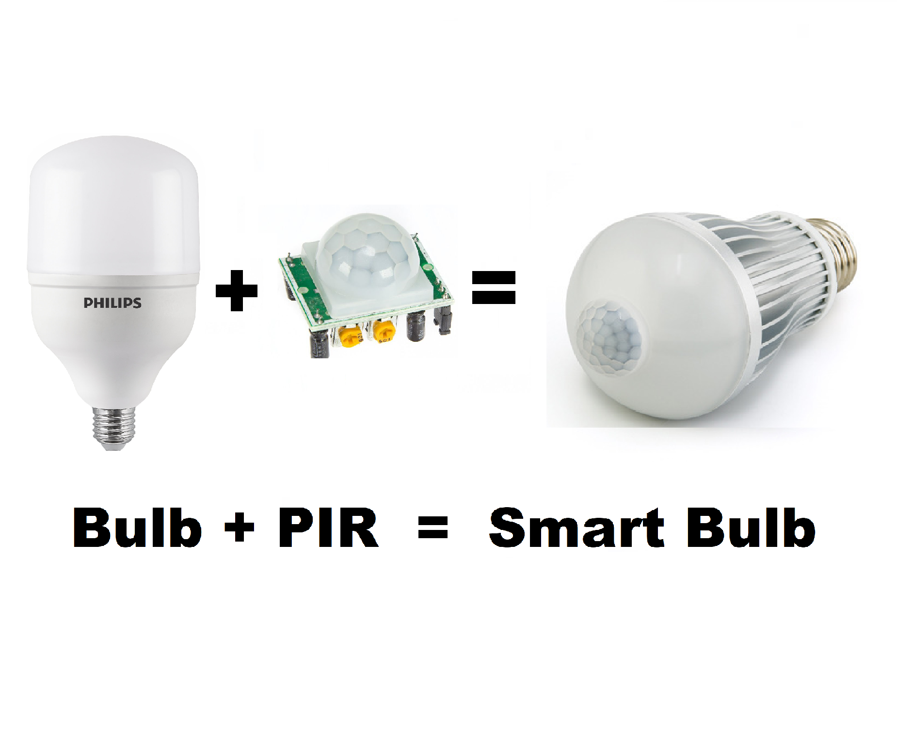
Turning a Bulb Into DIY Smart Light – PIR
I want a smart light, which can be turned on/off just by sensing the human body. Then I found some solutions, they are using PIR sensor to sense the motion as some additional circuitry for the timer. But most of them are rated below 2 stars. Because they are expensive, low build quality, fuse the bulb most of the time due to absent of driver circuit. Which led me to make a DIY solution of this.

I want to make these solutions for my store room and bathroom. Because these are the only places where I have to ON/OFF the light most of the time. And I will also allow to make the light on in daytime also. And here I am sharing my smart proximity infrared sensor light idea with you. To minimize the cost, we are not using any type of microcontroller for switching. PIR sensor itself come with a lot of features.

For store room I can left some wires out of the box because there is no one going to touch them. But in bathroom water drops can make a short circuit in the sensor. For that, In the next update of this tutorial I will come with a PCB prototype which can be placed into 3d designed case. I am not going to remove any circuit which disturb the LED behavior.

I am using JLCPCB for a long time and service they are offering in such a low price is quite amazing. Get your 5PCS prototype PCB boards just in $2.
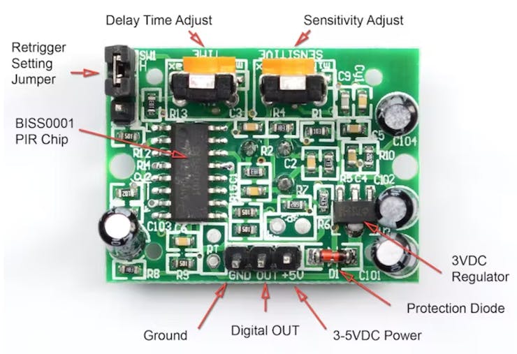
PIR sensor:
A passive infrared sensor (PIR sensor) is an electronic sensorthat measures infrared (IR) light radiating from objects in its field of view. They are most often used in PIR-based motion detectors. PIR sensors are commonly used in security alarms and automatic lighting applications.
PIR sensors detect general movement, but do not give information on who or what moved. For that purpose, an imaging IR sensor is required.
Features:
- Complete with PIR, Motion Detection.
- Dual Element Sensor with Low Noise and High Sensitivity.
- Supply Voltage – 5V.
- Delay Time Adjustable.
- Standard TTL Output.
- Further upgradeable with LDR
PIR sensors are commonly called simply “PIR”, or sometimes “PID”, for “passive infrared detector”. The term passive refers to the fact that PIR devices do not radiate energy for detection purposes. They work entirely by detecting infrared radiation (radiant heat) emitted by or reflected from objects.
Components required:
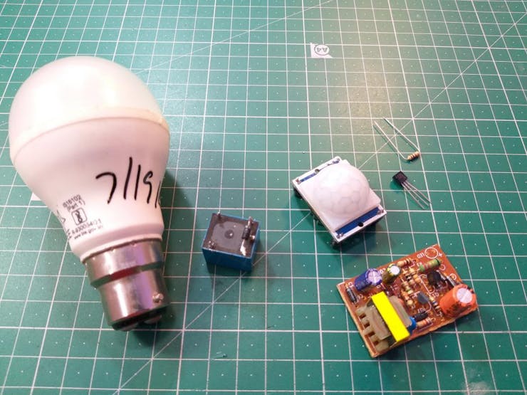
1) PIR sensor
2) 5v relay
3) 5v power SMPS
4) BC547 transistor
5) 1k resistor
6) 1N4007 Diode
7) Led Light bulb
8) Wires
Circuit diagram:
_z3i0ufyluu_M9ITZQVq8d.jpg?auto=compress%2Cformat&w=740&h=555&fit=max)
In the circuit transistor is used as a switch, with a 1k resistor on base to as current limiter. Relay is used to control the AC power after transistor switching. A flyback diode is connected to coil pins of the relay to avoid huge spikes during switching. Here I am using a 5v small SMPS module to control all the external circuitry. Transformer less solutions are not effective in this case.
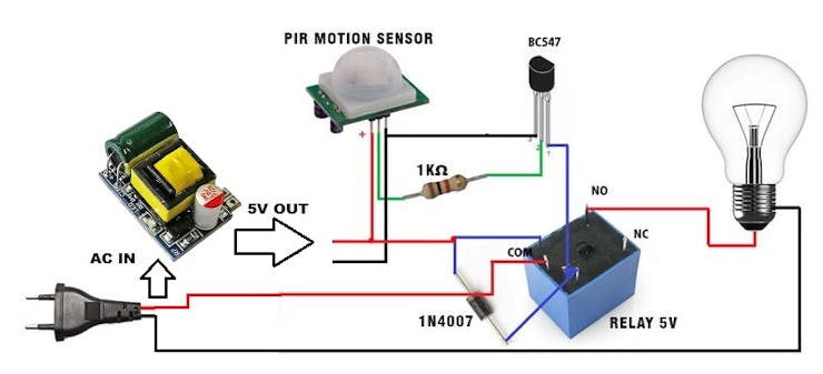
First the current from AC mains goes to the 5V SMPS module and COM pin of relay. Which turn on the sensor but output is zero initially. After sensing the motion, the OUT pin of sensor turn to high. Which is connected to the base of transistor with a resistor. This will turn on the transistor switch and power the relay coil. The relay then turns ON and COM pin get connected to Normally open pin. Which make the connection between the second wire of the led light bulb and hence turn on the bulb.
Steps involved upgrading bulb internally:
We need to modify the bulb with 3 wire interface. First, open the diffuser cover. This bulb is repaired by me, you can see the repairing tutorial of a LED bulb from here.
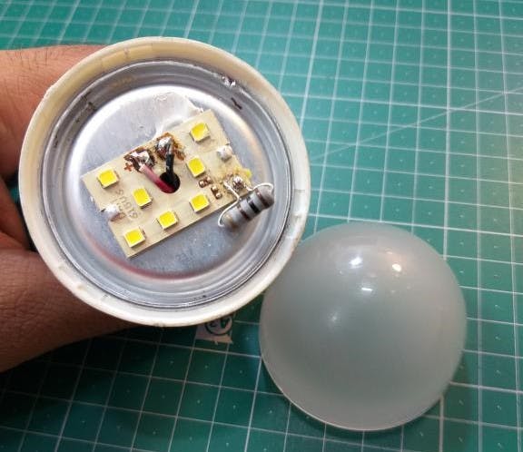
Then reveal the circuit, desolder the internal driver.
Cut the resistor and solder a wire after modifying. Further these wires will connect to relay module for switching.

Now make a hole through the aluminum body of LED and pull all the wires out of that.
Pack the bulb make all the connections of driver and LED.
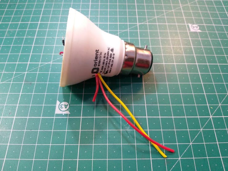
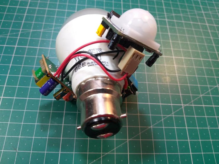
The internal work is done, no more modifications are need. We have three wires out of the box, 2 main power wires and a led bulb wire.
External modifications:
First make the connection of power wires to SMPS, Hot glue the SMPS over bulb.
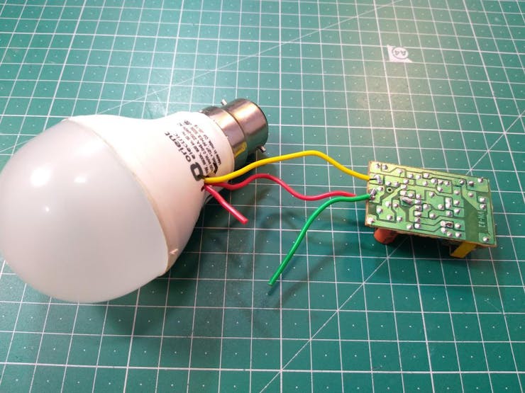
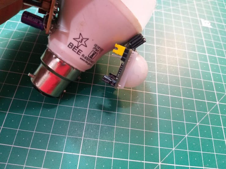
Then mount the PIR sensor in exact same direction you want to sense.
Glue the transistor and Relay at one side.
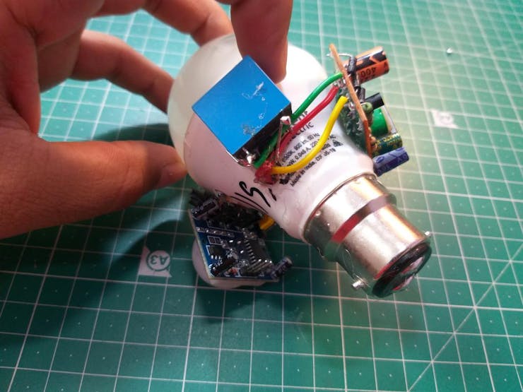
Make all the connections using the circuit diagram given above.
Tape properly all the Power wires and we are ready to test DIY bulb.
Working:
Now the bulb is working like the commercial solution available in market. Here the problem is just we are mounting all the component and circuit on the light bulb body. If it get fused then we have to do same work on the other bulb. But in the next section we will cover two things first to use it in a bathroom and to make a universal circuit case. In which we can plug the bulb and do the same thing but with a better method.
Once again a very thanks to JLCPCB. Sign-up now to JLCPCB and get free new user coupons of $54.